23
Electrical installation
Risk of injury from unintentional activation of the system and
an uncontrolled restart.
▶ Securesystemfromunintentionalactivation.
▶ Followinginstallation,ensureacontrolledrestart.
9.2. Electrical installation
with cable gland
DANGER!
Risk of electric shock.
▶ Beforereachingintothedevice,switchothepowersupply
andsecuretopreventreactivation.
▶ Observeapplicableaccidentpreventionandsafetyregulations
forelectricalequipment.
Procedure:
→ Open the Pneumatic Control Unit: unscrewing the transparent
capinananticlockwisedirection.
→ Push the cables through the cable gland.
→ Connectthewiresaccordingtothemodel(options)ofthe
Pneumatic Control Unit.
NOTE!
Damage or malfunction due to penetration of dirt and
humidity.
ToensuredegreeofprotectionIP65/IP67:
▶ Tighten the union nut on the cable gland according to the cable
sizeordummyplugsused.(ca.1,5Nm).
▶ Screw the transparent cap in all the way.
→ Tightenunionnutonthecablegland(torqueapprox.1.5Nm).
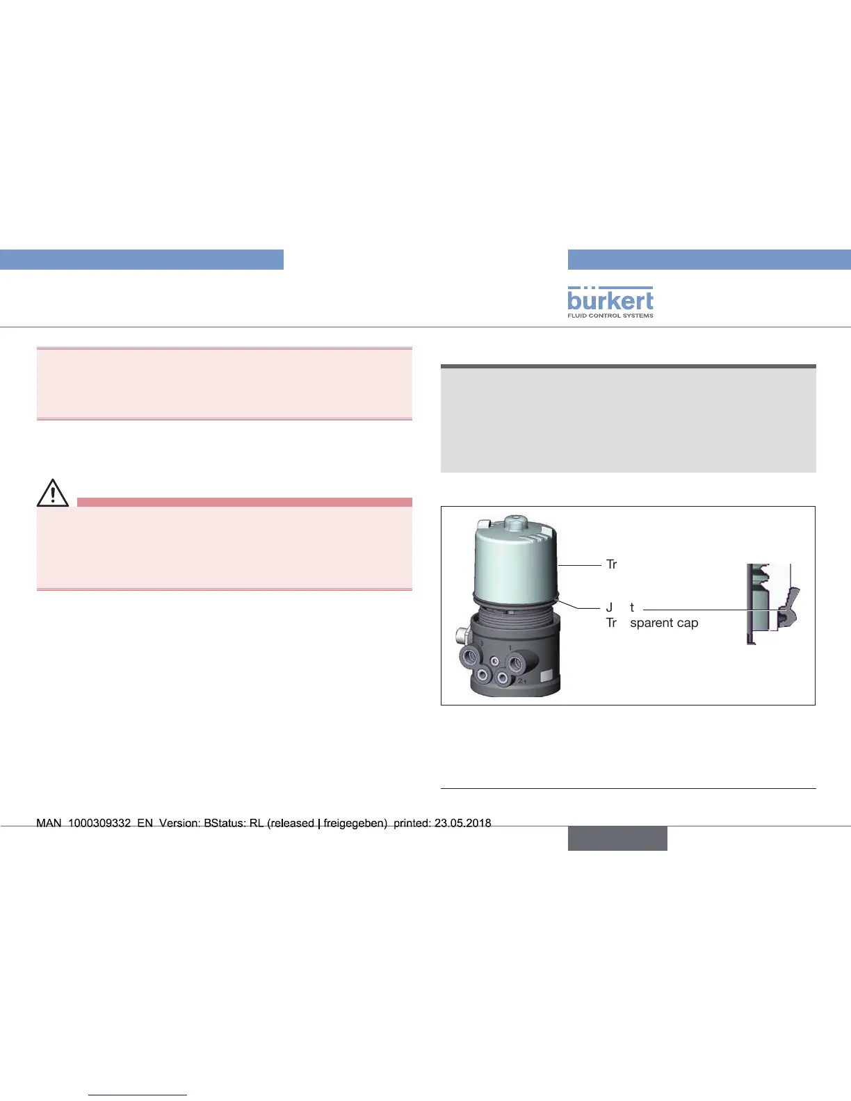
Transparent cap
Joint
Transparent cap
Fig. 19: Position of the seal in the transparent cap
→ Checkthatthesealiscorrectlypositionedinthetransparentcap.
→ Close the Pneumatic Control Unit (assembly tool: 674078
2)
).
2) The assembly tool (674078) is available from your Bürkert sales oce.