24
Electrical installation
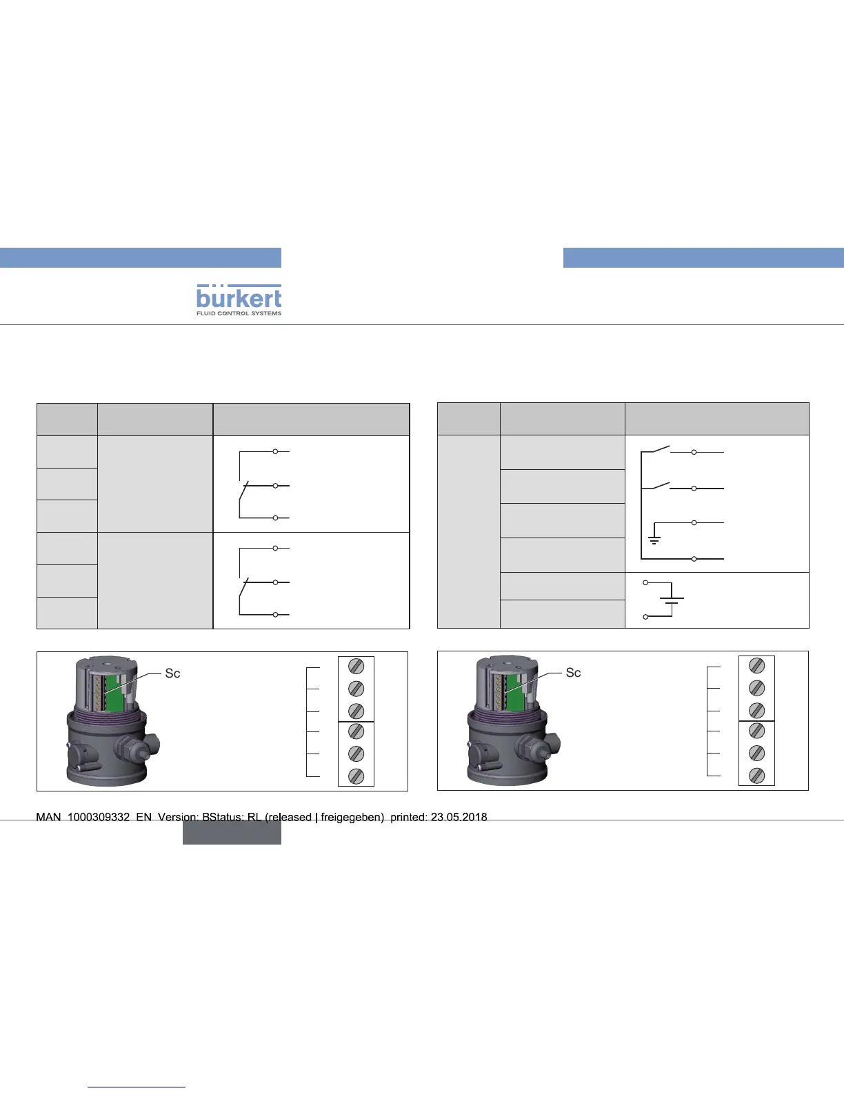
9.2.1. Connection diagram
with micro switches
(mechanical limit switches)
Terminal Conguration External circuit
1
Micro switch
top
1
2
3
NO
Joint
connection
NC
2
3
4
Micro switch
bottom
4
5
6
NO
Joint
connection
NC
5
6
Tab. 2: Connection diagram with micro switches
Screw terminals
1
2
3
TerminalNo
4
5
6
Fig. 20: Position of the screw terminals
9.2.2. Connection diagram
with 3-wire proximity switches
(inductive limit switches)
Terminal Conguration External circuit
1
INI+(24VDC)
Supply
4
3
2
1
Output 2
(24 V)
Output 1
(24 V)
GND
+24VDC
2
INIGND
Supply
3
INITop OUT
Output 1
4
INIBottom OUT
Output 2
5
Valvecontrol
0/24VDC
5
6
0/24VDC±10%
Residualripple10%
6
Valvecontrol
GND
Tab. 3: Connection diagram with 3-wire proximity switches
Screw terminals
1
2
3
TerminalNo
4
5
6
Fig. 21: Position of the screw terminals