26
Electrical installation
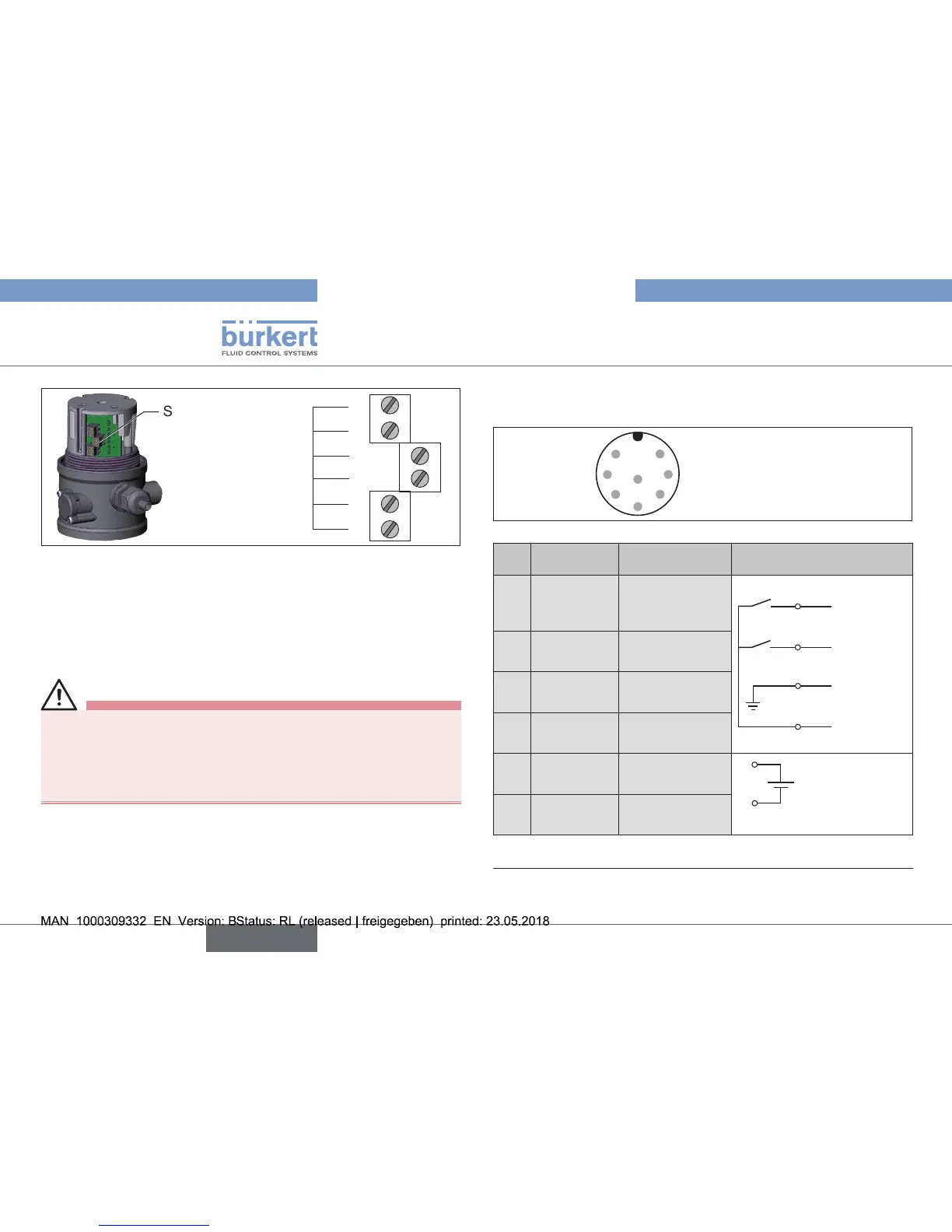
Screw terminals
1
2
3
TerminalNo
4
5
6
Fig. 23: Position of the screw terminals
9.3. Electrical installation with
circular plug-in connector
DANGER!
Risk of electric shock.
▶ Beforereachingintothedevice,switchothepowersupply
andsecuretopreventreactivation.
▶ Observeapplicableaccidentpreventionandsafetyregulations
forelectricalequipment.
→ Connect the pins.
Pin assignment
with 3-wire proximity switches (inductive limit switches)
1
2
5
64
73
8
Fig. 24: Circular connector M12x1, 8-pole
Pin
Wire
color
5)
Conguration External circuit
1 white
INIBottom
OUT
Output
2
1
3
4
Output 2
(24 V)
Output 1
(24 V)
GND
+24VDC
2
brown
INITop OUT
Output
3 green
INI-(GND)
Supply
4
yellow
INI+(24VDC)
Supply
5 grey
Valvecontrol0
/24V
5
6
0/24VDC
±10%
Residual ripple
10%
6 pink
Valvecontrol
GND
Tab. 6: Pin assignment with 3-wire proximity switches
5)
The indicated colors refer to the connecting cable available as an
accessory (919061)