29
Safety Positions
Theswitchcams(andswitchpoints)havenowbeenset.
→ Check the switching point(s) using suitable measuring
equipment.
→ Ifrequired,theswitchpointscanstillbenelyadjusted:Usinga
screwdriver,pushswitchcamstowardsthemiddle(see“Fig.27”).
→ Checkthatthesealiscorrectlypositionedinthetransparentcap.
(“Fig.19:Positionofthesealinthetransparentcap”,page23).
NOTE!
Damage or malfunction due to penetration of dirt and
humidity.
ToensuredegreeofprotectionIP65/IP67:
▶ Screw the transparent cap in all the way.
→ Close the Pneumatic Control Unit (assembly tool: 674078
7)
).
Switch cam
Fig. 27: Adjustment of the micro switch and the proximity
switches
8) The assembly tool (674078) is available from your Bürkert sales oce.
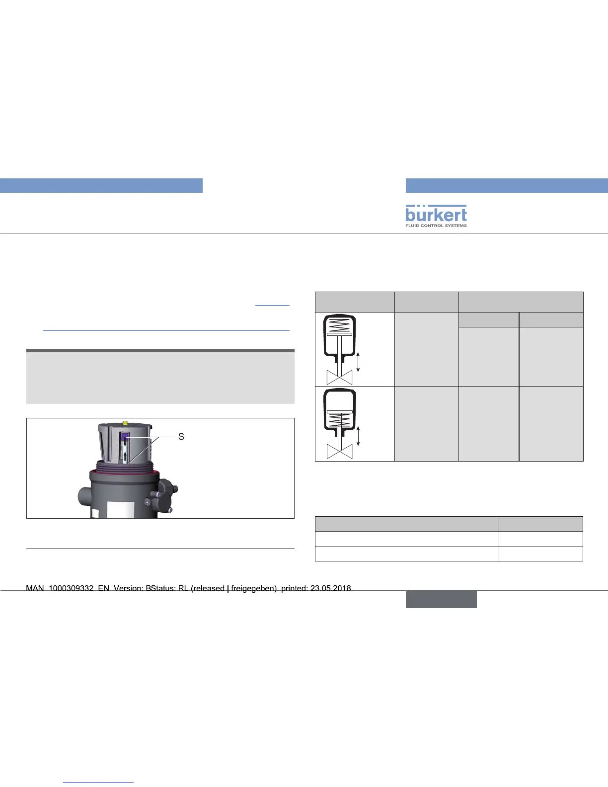
10. SAFETY POSITIONS
Safety positions after failure of the electric or pneumatic auxiliary
energy:
Operating mode Designation
Safety positions after failure
of the auxiliary energy
up
down
Single-acting
control
functionA
Electrical Pneumatic
down down
up
down
Single-acting
control
functionB
up up
Tab. 9: Safety positions
11. ACCESSORIES
Designation Order no.
ConnectioncableM12x1,8-pole 919061
Assembly tool 674078
Tab. 10: Accessories