28
Electrical installation
9.4.2. Display elements LEDs REV.2
Version
with 3-wire
proximity
switches
Version
with 2-wire
proximity
switches
Version with
2-wire prox-
imity switches
by NAMUR (Ex
version)
6)
End
position top
LED Top
is lit yellow is lit yellow
greeno
End
position
bottom
LED Bottom
is lit green is lit green
yellowo
Tab. 8: End position LEDs release version 2
Theversionwithmicroswitches(mechanicallimitswitches)does
notincludeanyLEDsforthepositionindicator.
7) In the case of the version with 2-wire initiators according to NAMUR
the LED function is inverse for technical reasons, i.e. the LED glows
when the end position is not reached and goes out when the end
position is reached.
9.5. Adjustment of the micro switches or
the proximity switches (option)
DANGER!
Risk of electric shock.
▶ Beforereachingintothedevice,switchothepowersupply
andsecuretopreventreactivation.
▶ Observeapplicableaccidentpreventionandsafetyregulations
forelectricalequipment.
Procedure:
→ Open the Pneumatic Control Unit: unscrewing the transparent
capinananticlockwisedirection.
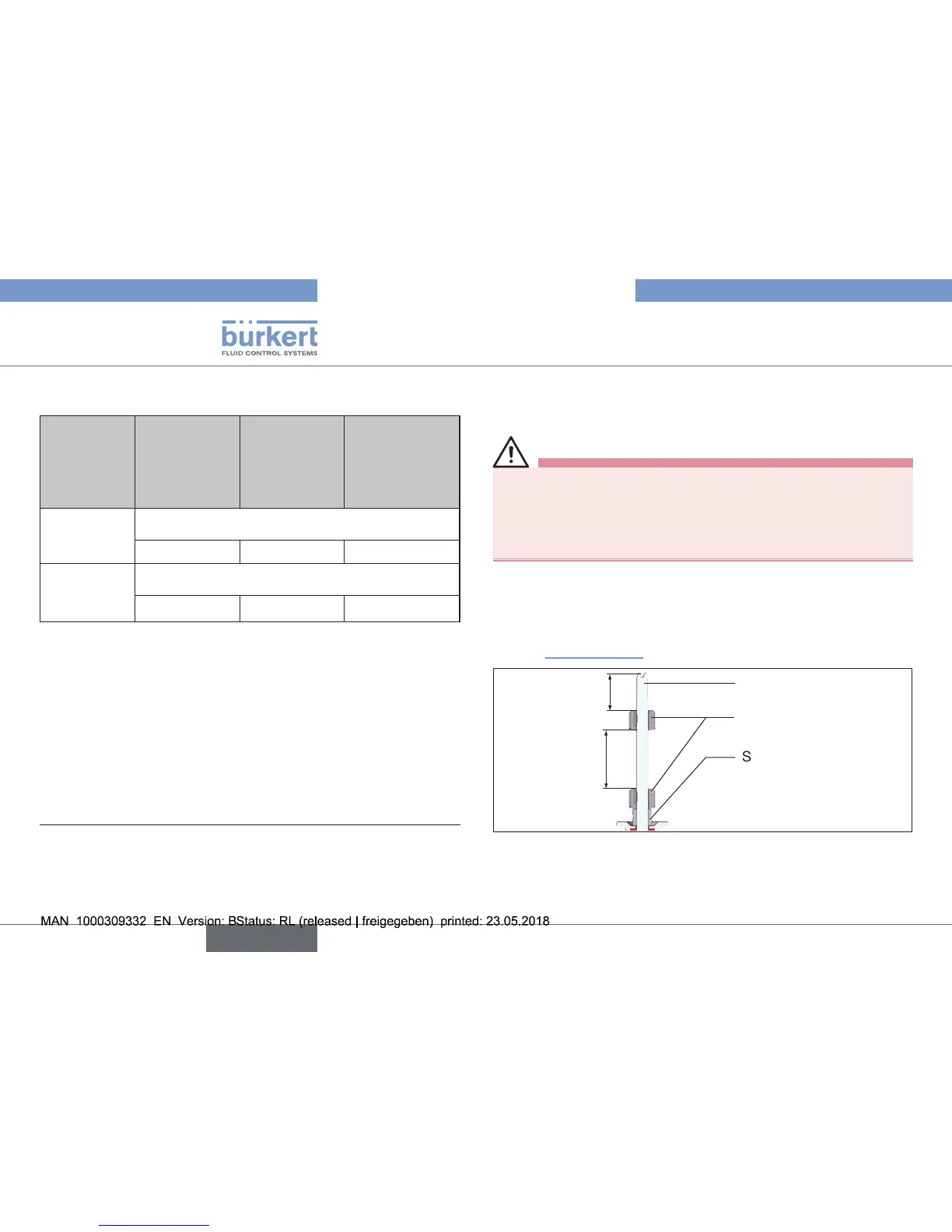
→ Ensure that the distance between both switch cams is maximum.
(see “7.Installation”).
Switch spindle
Switch cam
3
Spacersleeve
Maximum
distance
Fig. 26: Distance between the switch cams
→ Pressurizepilotairport1withcompressedair(5bar)or,iftted,
actuatethe hand lever of the pilot valvein the controlunit:
Actuatormovestothe2ndendposition.