15
Installation
7.3. Installation on process valves of
series 20xx
Procedure:
1. Install switch spindle
Transparent cap
Position indicator
Actuator
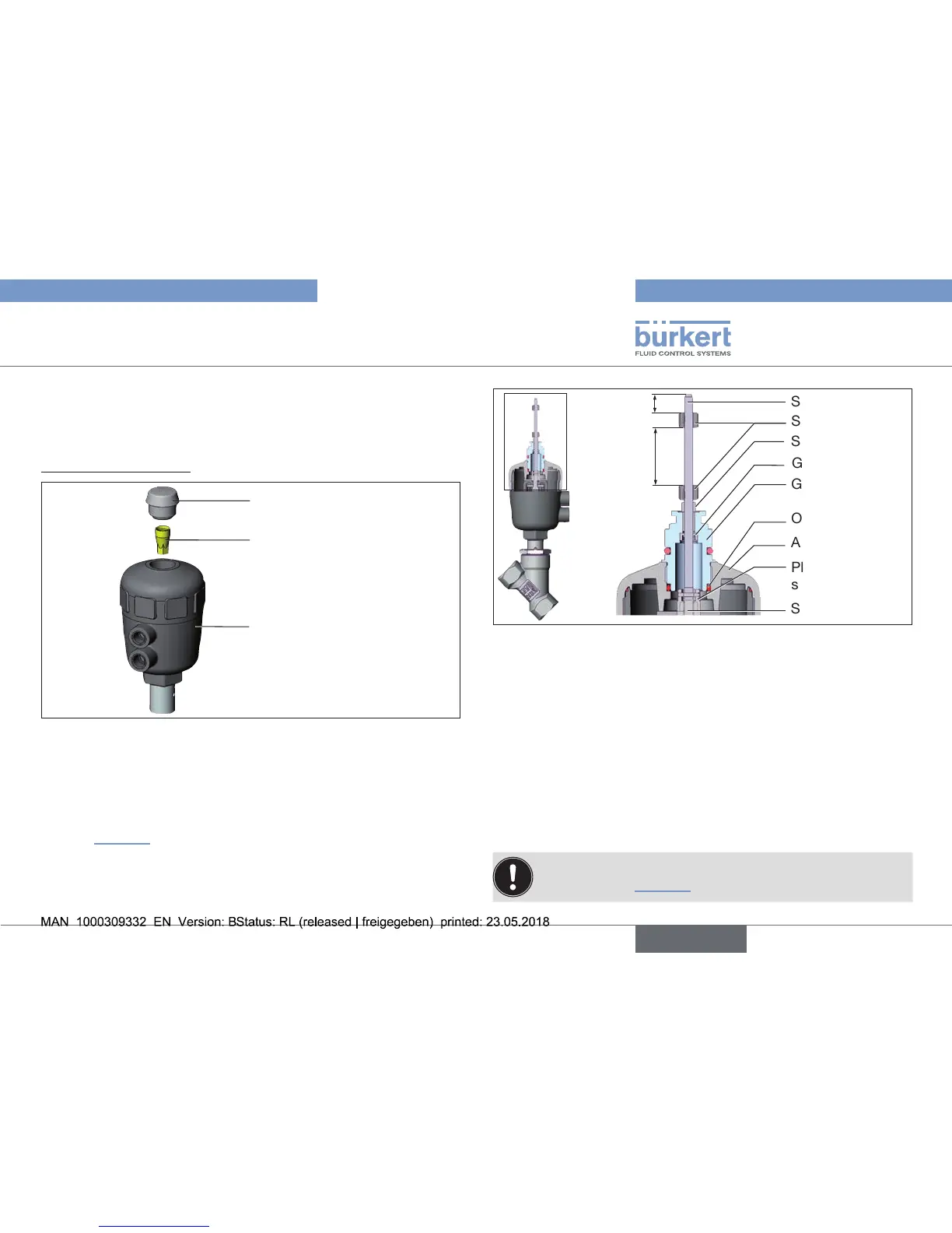
Fig. 10: Installation of the switch spindle (1), series 20xx
→ Unscrew the transparent cap on the actuator.
→ Usingahexagonsocketkey,unscrewtheorange/yellowposition
indicatorfromtheinsideoftheactuator.
→ PresstheO-ringdownwardsintothecoveroftheactuator
(see “Fig.11”).
→ Manually screw the switch spindle (and the plugged-on guide
element)togetherwiththeplasticpartontothespindleofthe
actuator,butdonottightenspindleyet.
Guideelement
O-ring
Plasticpartofthe
switch spindle
Switch cam
Switch spindle
Spindle (actuator)
Actuatorcover
Groovering
3
Spacersleeve
Maximum
distance
Fig. 11: Installation of the switch spindle (2), series 20xx
→ Tighten the guide element with a wrench SW19 into the actuator
cover(torque:8.0Nm).
→ Tighten the switch spindle on the spindle of the actuator.
Todothis,thereisaslotontheupperside(torque:1.0Nm).
→ Pushspacersleeveonto the switchspindle up totheguide
element.
→ Position switch cams on the switch spindle:
→ Pushlowerswitchcamuptothespacersleeve.
→ Pushupperswitchcamuntil3mmfromthestartoftheswitch
spindle.
Ensure that the distance between both switch cams is
maximum (see “Fig.11”).