25
Electrical installation
9.2.3. Connection diagram
with 2-wire proximity switches
(inductive NAMUR limit switches)
Terminal
Congu-
ration
External circuit
1
INITop+
NAMUR-
Sensor
Explosion
protected area
Non-hazardous
area
+8,2VDC
0 V
R
1/3
2/4
3)
2
INITop-
3
INIBottom
+
4
INIBottom-
5
Valvecontrol
+
5
6
PA
Explosion
protected area
Non-hazardous
area
+
Safetybarrier
4)
6
Valvecontrol
GND
Tab. 4: Connection diagram with 2-wire proximity switches
3) (Recommended by NAMUR) Observe the max. values of the
intrinsically safe circuits in the ATEX additional instructions.
4) Signal from barrier see PTB 07 ATEX 2048
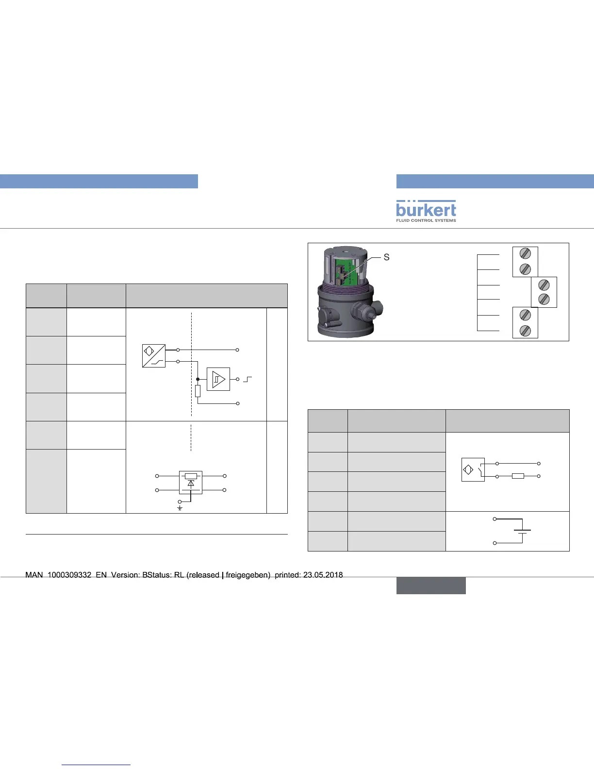
Screw terminals
1
2
3
TerminalNo
4
5
6
Fig. 22: Position of the screw terminals
9.2.4. Connection diagram with 2-wire
proximity switches 24 V (inductive limit
switches, normally open)
Terminal Conguration External circuit
1
INITop+
+
–
load
1/3
2/4
2 INITop-
3 INIBottom+
4 INIBottom-
5
Valvecontrol+
5
6
6 ValvecontrolGND
Tab. 5: Connection diagram with 2-wire proximity switches 24 V