13
Installation
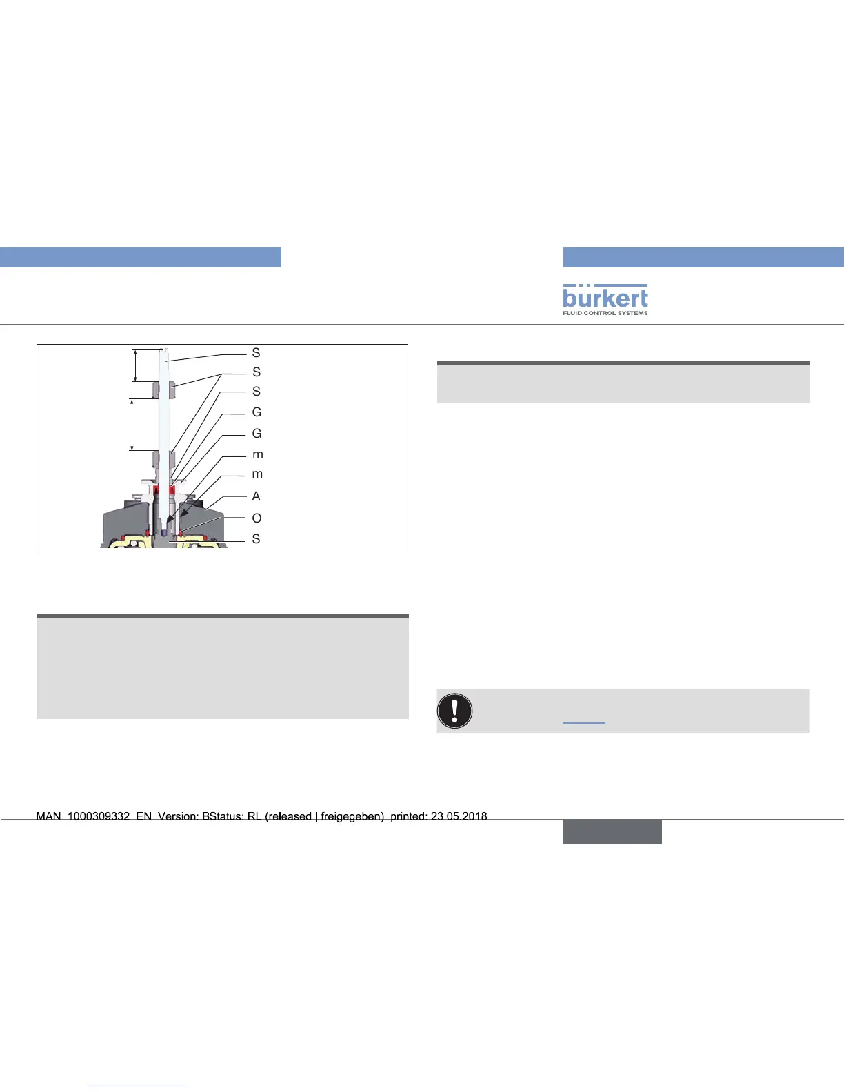
O-ring
Spindle extension
Guideelement
Actuatorcover
Groovering
Switch spindle
Switch cam
3
max.5Nm
max.1Nm
Spacersleeve
Maximum
distance
Fig. 7: Installation of switch spindle (2), 21xx series
NOTE!
Improper installation may damage the groove ring in the
guide element.
Thegrooveringisalreadybepre-assembledintheguide
elementandmustbe“lockedintoposition”intheundercut.
▶ Wheninstallingtheswitchspindle,donotdamagethegroove
ring.
→ Push the switch spindle through the guide element.
NOTE!
Screw locking paint may contaminate the groove ring.
▶ Donotapplyanyscrewlockingpainttotheswitchspindle.
→ Tosecuretheswitchspindle,applysomescrewlockingpaint
(Loctite290)inthetappedboreofthespindleextensioninthe
actuator.
→ CheckthattheO-ringiscorrectlypositioned.
→ Screwtheguideelementtotheactuatorcover
(maximumtorque:5Nm).
→ Screwswitchspindleontothespindleextension.Todothis,
thereisaslotontheupperside(maximumtorque:1Nm).
→ Pushspacersleeveonto the switchspindle up totheguide
element.
Position switch cams on the switch spindle:
→ Pushlowerswitchcamuptothespacersleeve.
→ Pushupperswitchcamuntil3mmfromthestartoftheswitch
spindle.
Ensure that the distance between both switch cams is
maximum (see “Fig.7”).