17
Installation
→ Screw the plug-in hose connectors onto the Pneumatic Control
Unit and the actuator.
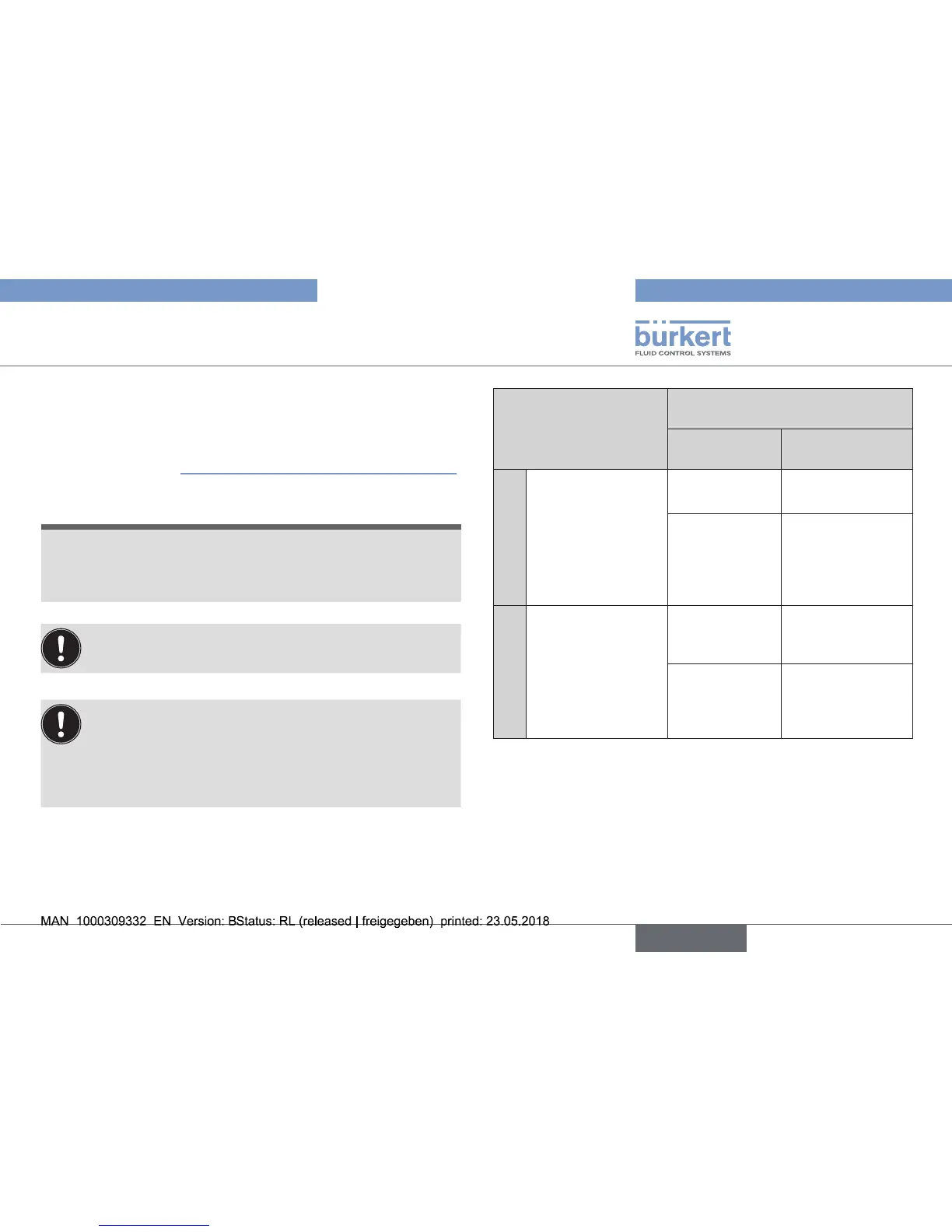
→ Usingthehosessuppliedintheaccessorykit,makethecon-
nection between the Pneumatic Control Unit and the actuator
withthefollowing“Tab.1:Pneumaticconnectiontoactuator”.
NOTE!
Damage or malfunction due to ingress of dirt and moisture.
▶ TocomplywithdegreeofprotectionIP65/IP67,connectthe
pilotairoutletwhichisnotrequiredtothefreepilotairportof
the actuator or seal with a plug.
“Inrestposition”meansthatthepilotvalvesofthePneu-
matic Control Unit Type 8697 are isolated or not actuated.
If theambient air is humid, a hose can be connected
between pilot air outlet 2
2
ofthePneumaticControlUnit
andtheunconnectedpilotairportoftheactuatorforcontrol
function A or controlfunction B.As a result,the spring
chamberoftheactuatorissuppliedwithdryairfromthe
ventductofthePneumaticControlUnit.
Control function Pneumatic connection Type 8697
with actuator
Pilot air outlet
Type 8697
Pilot air port
actuator
A
Processvalve
closed in rest
position
(byspringforce)
2
1
lower pilot air port
oftheactuator
2
2
should be con-
nected to the
upper pilot
airportofthe
actuator
B
Processvalveopen
in rest position
(byspringforce)
2
1
upper pilot
airportofthe
actuator
2
2
should be con-
nected to the
lower pilot air port
oftheactuator
Tab. 1: Pneumatic connection to actuator