8
Description of system
Optical position indicator:
The device status is displayed on the Pneumatic Control Unit
(yellowmark).
Option: Electrical position feedback
Optionallymechanicallimitswitches(microswitches)orinductive
proximityswitchescanmeasurethevalveposition.
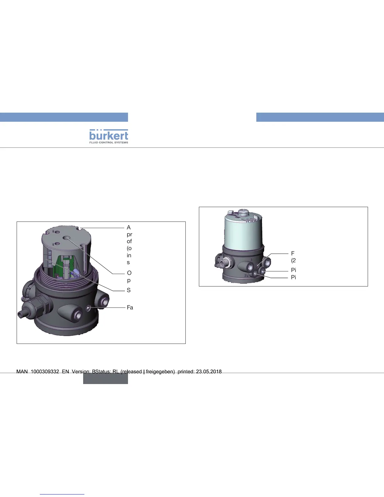
View without transparent cap:
Fastening screws (2x)
Screw terminals
Assemblyshaftfor
precision adjustment
oftheswitchcams
(onlyformodelwith
inductiveproximity
switches)
Openingforoptical
position indicator
Fig. 2: Conguration and function (2)
5.1.2. Model for control of process valves
belonging to the 20xx series
A special model enables the Pneumatic Control Unit Type 8697 to
beattachedtoprocessvalvesbelongingtothe20xxseries.
Thismodelhasadierentpneumaticconnectionmodulesothat
thepilotairportscanbeconnectedtotheoutsideoftheactuator.
Pilot air outlet 2
1
Fastening screws
(2x)
Pilot air outlet 2
2
Fig. 3: Connection module for process valves, 20xx series