38
Installation
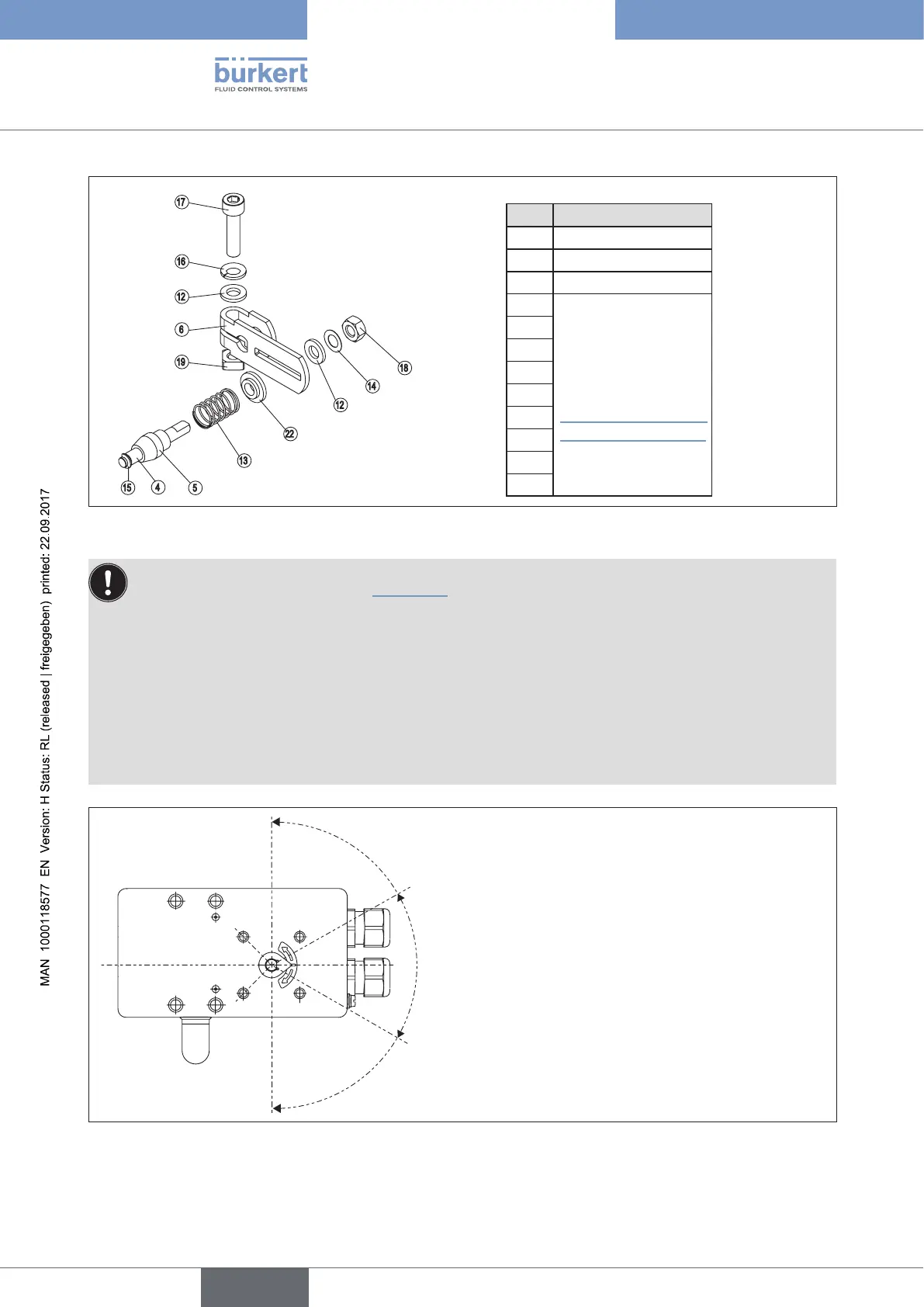
Legend:
No. Name
4 Driver pin
5 Conical roller
6 Lever
12
For a description of
the numbering,
refer to
“Table 11: Attachment
kit for linear actuators”
13
14
15
16
17
18
19
22
17
16
12
6
19
18
14
12
22
5
4
13
15
Figure 13: Assembling the lever
The gap between the driver pin and the shaft should be the same as the actuator stroke. As a result, the
lever has a swing range of 60°. (see “Figure 14”).
Rotation range of the position sensor:
The maximum rotation range of the position sensor is 180°.
Swing range of the lever:
To ensure that the position sensor operates at a good resolution, the swing range of the lever must be at
least 30°.
The swing movement of the lever must be within the position sensor rotation range of 180°.
The scale printed on the lever is not relevant.
60°
Ideal swing range
of the lever
(min. 30° / max. 180°)
The swingmovement of
the lever must be within
the position sensor rotation range of 180°.
180°
Maximum swing
range of the lever
Figure 14: Swing range of the lever
→ Attach lever to the shaft of the Type 8792/8793 and screw tight.