Connection, installation / mounting
Product manual 2CKA001473B8291
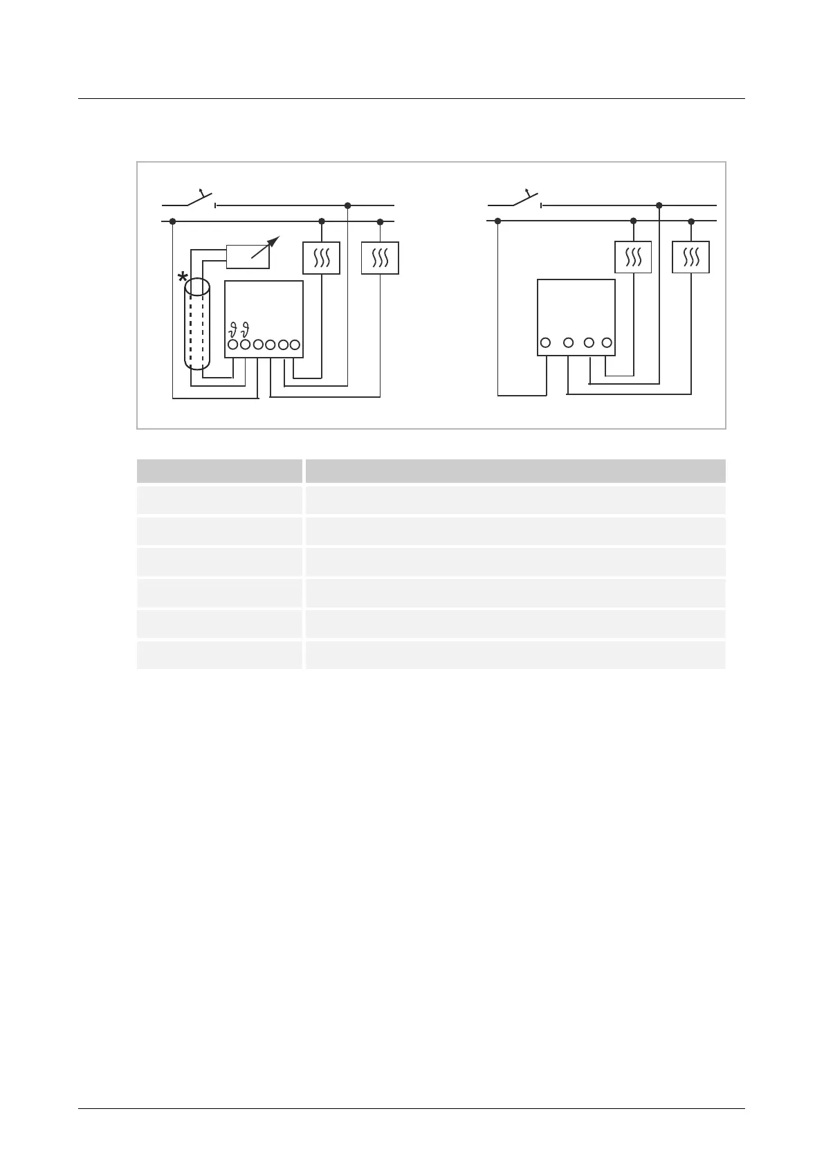
6.3 Electrical connection
1098 UF-101 1098 U-101
Fig. 4: Circuit diagrams
Terminal designation Assignment
L Phase
N Neutral conductor
1 Output for controlling the heating load
2 Output for controlling the cooling load
ϑ Remote sensor connections
* The sensor cable must be installed in a protective cable duct.