Commissioning | 7
Instruction Manual MINK MV 0500-0600 B_EN_en 21 | 40
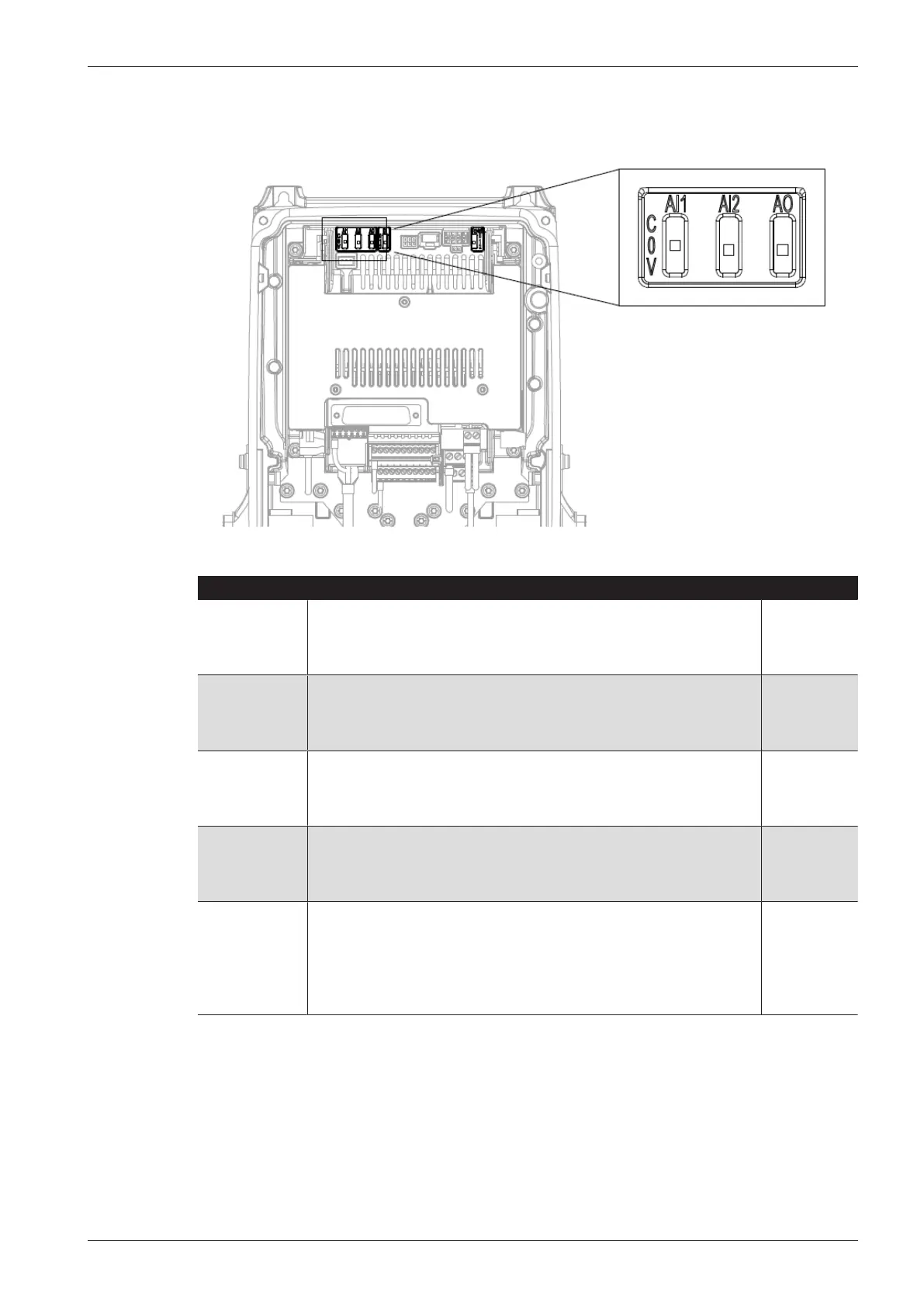
7.1.2 DIP-Switch
DIP-Switch Description Standard
AI1 C = Analog input 1 operates in current mode (2 … 20 mA)
0 = Analog input 1 located in test mode
V = Analog input 1 operates in voltage mode (2 … 10 V)
V
AI2 C = Analog input 2 operates in current mode (2 … 20 mA)
0 = Analog input 2 located in test mode
V = Analog input 2 operates in voltage mode (2 … 10 V)
C
AO1 C = Analog output operates in current mode (2 … 20 mA)
0 = Analog output located in test mode
V = Analog output operates in voltage mode (2 … 10 V)
C
DI 0 = Digital input is isolated by grounding
1 = Common grounding of digital input is connected to 24 V
2 = Common grounding of digital input is connected to ground
2
RS 485 0 = Connection resistance 120 Ohm is connected
1 = Pull-Up and Pull-Down resistance of 10k Ohm for bias voltage is
connected
2 = No timing settings and no bias voltage resistance are connect-
ed
2