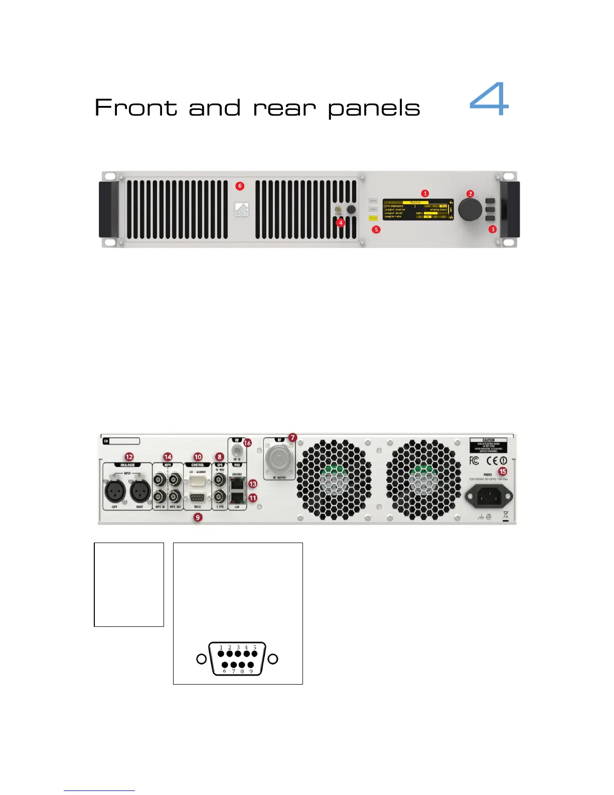
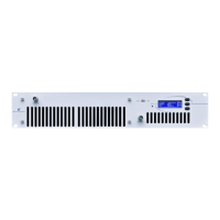
1. OLED display – shows status and used for programming.
2. Menu navigation knob – turn to highlight and press to select options.
3. Push-buttons for menu navigation/selection, and RF and telemetry on/off.
Left buttons are illuminated to show status.
4. RF sample port – for connection to test equipment.
5. LED indicators to show status.
6. Removable front panel – provides access to washable air filter and hot-
swappable power supplies.
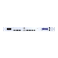
7. RF output connector
8. External reference inputs – 10MHz
and 1pps.
9. RS-232 serial interface
10. GPIO / parallel remote control
connector
11. Ethernet port
12. Analog Program audio inputs
13. Digital (AES-EBU) or digital mpx input
and output
14. Composite baseband (mpx) inputs
and outputs
15. AC power connector
16. Rx antenna connector (optional)