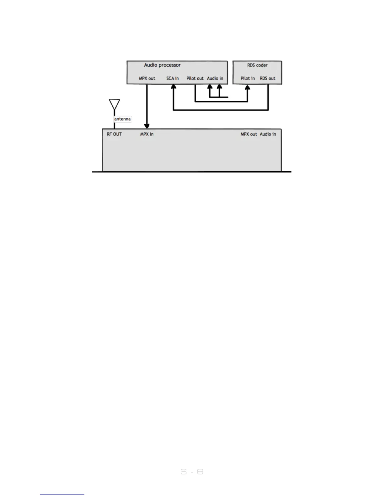
6.2.4 Transmitter with an external audio processor and RDS (sidechain connection)
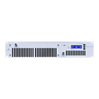
1. Place the transmitter in a well ventilated space.
2. Connect the antenna to the RF output connector on the back of the transmitter.
3. Connect the MPX output of your audio processor (or stereo generator) to the
MPX input on the back of the transmitter.
4. Connect the Pilot output of your audio processor (or stereo generator) to the
pilot/reference input on your RDS encoder.
5. Connect the MPX output of your RDS encoder to the SCA input on your audio
processor.
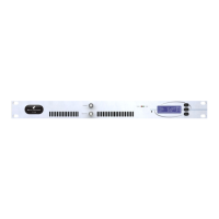
6. Plug the power cord into the power supply module on the rear panel of the
transmitter.
7. Connect the required remote control / monitoring ports (Ethernet, RS232,
Alarms/Triggers port).
8. Once the transmitter is operating, set the correct carrier frequency and power
from the RF settings menu. Check reflected power is OK.
9. In the RF Settings menu, set MPX Source to MPX Input 1.
10. Check the modulation level - if the modulation level is low, adjust the MPX output
level on your audio processor (or stereo generator). The maximum modulation
should not exceed 75kHz.
11. Check the documentation that came with your audio processor on how to
set/check the proper pilot injection level.
12. Check the documentation that came with your RDS encoder on how to
set/check the proper RDS injection level.
In this setup, the audio stereo multiplex is generated in the audio processor. The RDS
data is fed into the audio processor where it is combined with the audio multiplex. This
combined signal is fed directly into the transmitter exciter. Note that the transmitter’s
onboard processing will have no effect on the signal in this configuration.
This is the best connection in terms of pilot and RDS subcarrier phase synchronization and
MPX spectrum cleanliness, if you’re not using the V3’s internal RDS and stereo
generators.