15
EN
UV radiation and heat sources above 40 °C).
Caution: keep plastic components free from oil and
fat, solvents and acids and base cleaners.
5. Installation
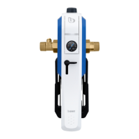
5.1 Check the direction of ow and change if
necessary
In the delivery state the direction of ow is from
left to right (heed ow direction arrow – visible on
the brass body below the handle). It is possible to
change this prior to lter installation – without con-
nection screw joints and manometer:
- Turn stopcock/
unlocking device (6)
to the ‘open‘ position
(90° clockwise)
- Open lever (1) by
approx. 80° - 90°
- Remove the black
cover on the reverse
of the lter
- Loosen bolt
(anti-rotation device)
- Rotate the brass
housing by 180°
- Reinsert the bolt
(anti-rotation device)
The direction of ow is
now from right to left.
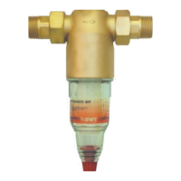
5.2 Install lter
Mount the screw connection including the at gasket
enclosed with the lter – the screw connection with
the backow preventer must be positioned on the
input side (only E1 HWS). Seal the manometer (5)
which is also enclosed (only E1 HWS). Then install
the lter according to the nominal width into the simi-
larly dimensioned cold water pipe and upstream from
the objects to be protected.
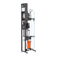
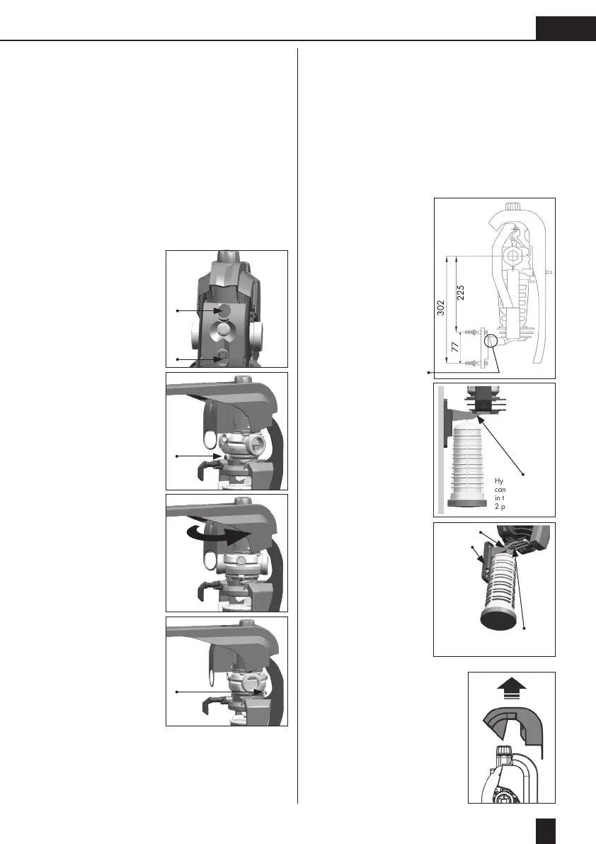
5.3 Install wall mounting
The wall mounting is pre-installed on the lter. It is
xed to the wall using the supplied bolts and dowels
(2 x KA40 or Ø 6 mm) in the wall.
- Installation of wall
mounting only after
installation of the
lter
- Distances for installa-
tion of wall mounting
according to the
sketch
- Caution: If lter * is
closed, then position
above in wall moun-
ting.
- A hygienic vault
(lter cup + lter
element + lid) can
be suspended in the
mounting
- The distance from the
wall varies between
80 - 120 mm. Two-
part wall mounting.
6. Commissioning
Check lter for proper instal-
lation.
6.1 Set pressure reducer (only
E1 HWS)
The pressure reducer is under
the cap.
two part wall
mounting
Oblong hole for setting the distance
from the wall 80 mm - 120 mm
Hygienic vault
can be suspended
in the mounting
2 part design