16
EN
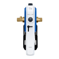
Simply remove the cap (2) to reach the pressure re-
ducer. The pressure reducer is set to a back pressure
of 4 bar at the factory. To change the back pressure,
loosen the locking screw (10) and turn the rotary
knob (11). The back pressure can be changed by
turning the setting knob (11) (control range 2 - 6
bar).
Clockwise rotation = higher back pressure.
Anti-clockwise = lower back pressure.
The manometer (5) displays the back pressure. Du-
ring setting, an outlet valve downstream from the
pressure reducer must be briey opened and closed
again a number of times. When water is removed,
the back pressure is temporarily reduced. The back
pressure must not exceed 80 % of the response pres-
sure of the hot water safety valve (DIN 1988-200).
6.2 Insert batteries in the
lter change display (7):
For impeccable, hygienic
enjoyment of drinking water
in accordance with the stan-
dards, the lterelement must
be replaced at least every
6 months. The installed LED
display gives a timely war-
ning by means of a visual si-
gnal. The supplied batteries
must be inserted for commis-
sioning:
- Remove the cap (2)
- Open the battery com-
partment cover using a
screwdriver
- Insert the batteries (2
x AAA): an automatic
function test occurs (5 x
slow ashing)
- Close battery compart-
ment and replace cover
-
The lter is now ready
for operation.
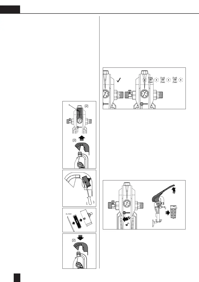
7. Operation
The lter and pressure regulation functions work
completely autonomously without the need for ope-
ration. For impeccable, hygienic enjoyment of drin-
king water in accordance with the standards, it is
only necessary to replace the lter element at least
every 6 months. The integrated LED display gives a
timely warning by means of a visual signal: the red
LED ashes every 5 seconds.
- Flashing interval after 6 months/ 182 days have
elapsed: a red LED ashes every 5 seconds.
- Flashing period: after expiry of time until lter
change or reset occurs.
7.1 Replace lter and check batteries
With the new single lever operation, replacing the
lter element is easy and only takes seconds:
1. Slowly unlock the stopcock (6), thus
simultaneously and automatically stopping
the water (A1).
Note: The stopcock (6) is for maintenance
purposes only, i.e. for replacing the lter element.
It is not intended as the main shut-off for the water
supply.
2. Lift the single lever to approx. 130° (B1) – Pull
out the supporting core, incl. lter cup and lter
element (C1).
B1
A1
C1
 Loading...