26
EN
6
Donotpluginthepowersupplyunit(3)until
startup.
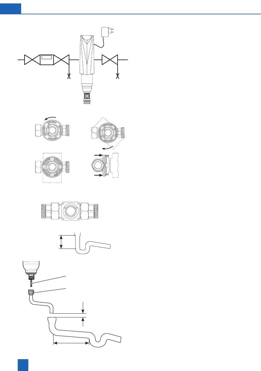
Installthe lter in the coldwater pipes upstream
of the objects to be protected (see installation dia-
gram).Alwaysprovidestopvalves.
Install the connecting module or connector in the
directionofowinahorizontalorverticalcoldwater
pipe(observedirectionofowarrow).
1. Turn the black retaining ring to the left limit stop.
2. Presstheprongsofthedeviceintothespaces
provided
3. Rotate the device clockwise 45° to the limit stop.
4. Pull the black retaining ring with both hands
towards the device until it clicks into place. The
device cannot now be rotated unintentionally.
To release the lter,press the retaining ring
towards the connecting module.
1. Screwtheltertotheconnectorusing4hexa-
gon screws and the seal (screws and washers
included).
2. Checkthesealforpropert.Tightenthescrews
evenly and crosswise.
Route the wastewater connection to the drain so
thatnoreuxoccurs.
Donotbendtheventtube(5)whenchanging
tothehoseconnection(6).
Theushingwaterhosemustbesecuredat
a distance of at least 20 mm from the highest
possiblewastewaterlevel(freedischarge).
> 400 mm
0 0 0
Σm
3
> 20 mm
> 1 m
6
5
4.
2.1.
3.