CONNECTIONS
Connect the hydraulic block for softeners BWT PERLA PRO XS.
1 = Inlet water to be treated tapped 1’’ gas
2 = Outlet water to be treated tapped 1’’ gas
3 = Discharge of regeneration water tubing 12/16
4 = Connection with brine regulator tubing 6/8
The connections to the softener be removable accessible to facilitate any maintenance operations. The
pipes be properly supported so that no effort or constraint affects the appliance.
WATER INLET AND TREATED WATER OUTLET
The inlet pipe for the water to be treated must be sufficiently sized to be able to provide the required pro-
duction flow rate and the minimum regeneration flow rate.
In order to control the pressure, it is recommended to install a manometer upstream of the softener.
In addition, we advise fitting a filter upstream of the softener so as to protect it from foreign bodies that
could disturb its operation.
It is the responsibility of the installer to verify all specific sanitary regulations that could be force on the
installation location and comply with them.
Sampling must always be provided upstream and downstream of the softener.
The softener BWT PERLA PRO XS must be protected from any water backflow by a suitable backflow preven-
ter device, fitted downstream of the appliance on the treated water pipe.
The installation upstream and downstream of the softener must not cause “water hammer” (as appro-
priate, provide effective water hammer arresters).
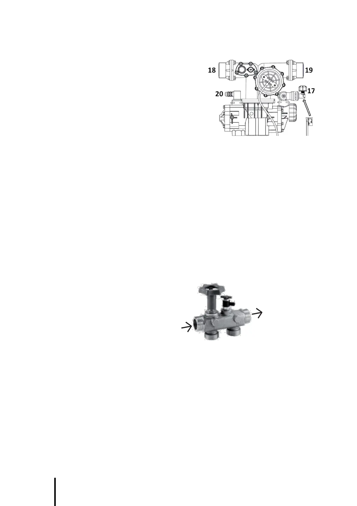
BWT recommends the implementation of the by-pass module and associated hoses. the system includes :
- By-pass
- Sample valve
Inlet water
Outlet water
REGENERATION WATER DRAINAGE
Drainage of softener regeneration water must be done using the hose rep 3.
This hose being in pressure during regeneration, it must be fixed to the softener connector using the collar sup-
plied. Also provide fixing for this hose along its length so as to avoid any force being applied to the softener valve.
The regeneration water drain pipe must use the shortest and simplest route possible. It must allow the drainage
at the flow 50 m/h with one pressure loss (free flow) not exceed 3 meters water column (0,3 bar).
In accordance with the requirements of the sanitary regulations, a pressure break at least equal to 2 cm must
be provided between the softener pipe and the drain pipe.
In the event of drainage through a recovery sump and a lifting pump, dimension the equipment so as to avoid
risks of flooding the room (in the event of unexpected stoppage of the lifting pump during regeneration).
WARNING : In the event of a power outage during a regeneration, the flow to the softener sewer is not
stopped.