SALT TANK OVERFLOW DRAIN
The salt tank is fitted with a safety overflow that must be connected into either a gutter or a drain collector.
The discharge must be done by gravity without pressure loss. It is imperative that a pressure break of at
least 2 cm is created in accordance with sanitary regulations.
BRINE REGULATOR CONNECTION
The brine regulator is situated in the brine well (grey PVC cylinder) inside the salt tank. Connect the hose
supplied to the regulator (wing nut) and to the softener.
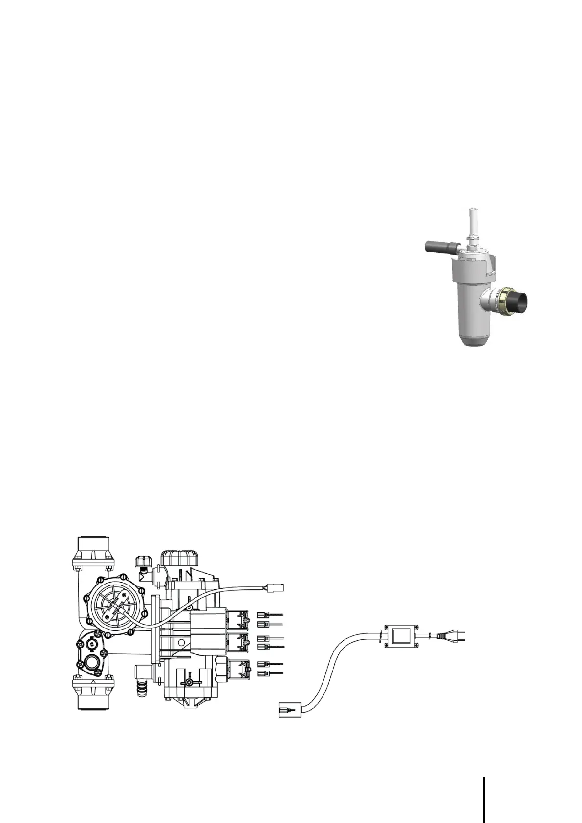
U-BEND CONNECTION
Connect the hose for the regeneration water discharge (1) to the upper ribbed
connector and fix the “Serflex” clamps at both ends.
This hose should not be longer than 4 meters and should without wrinkles.
Connect the salt tank overflow hose to the side orifice (2).
The overflow of the salt tank must be in gravity flow.
On the self-locking connector (3), 40 millimeters in diameter,
attach a PVC pipe to the drain (minimum diameter of 40 mm).
Provide a minimum 2% slope to ensure gravity flow
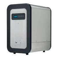
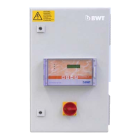
CONTROL BOX
The A5X microprocessor control unit is used to control a softener.
A 5-key keypad on the front panel gives access to the programming of the various sequences necessary for
the operation of the softener and to program the regeneration delays.
It is delivered with an external transformer delivering very low voltage currents necessary for the operation
of electronics and regenerative solenoid valves.
It will be necessary to bring a 230-volt single-phase electric wall socket (European standards) close to the
cabinet (2.5 meters maximum) (see also the technical operating conditions).
ELECTRICAL WIRING
ILS for meter
EV1
EV2
EV3
Blue
Brown
Blue
Black
Blue
Red
Power supply
Electronic card power