iNetVu™ Service Manual Page 74 of 109
10)
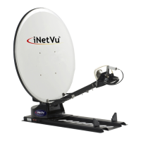
Verify Focal Point (ABCD) Geometry. Measure from the dimples on the
top and bottom edge of the reflector, and ensure that dimensions are within ¼ ”
of the values below.
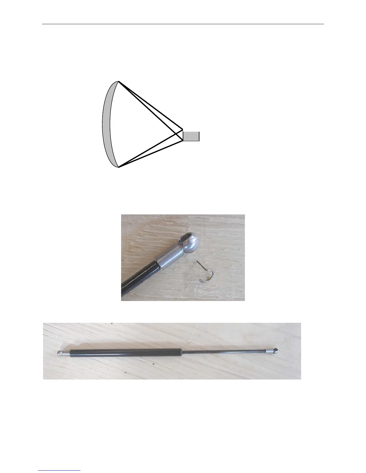
11) Remove the clips from the Ball Joints at the ends of the Gas Springs and
place aside.
Fig. 33: Removed Clip from Ball Joints
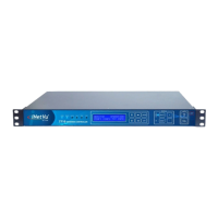
Fig. 34: Gas Shock Spring
12)
Snap-on the thicker end of the Gas Spring to the Reflector’s Gas Spring
Brackets. Once this end is snapped into place, re-insert clip.
Thin End
Thick End
A – 33.72”
B – 36.97”
C – 51.54”
D – 48.28”
Feed Horn
Reflector