iNetVu™ Service Manual Page 78 of 109
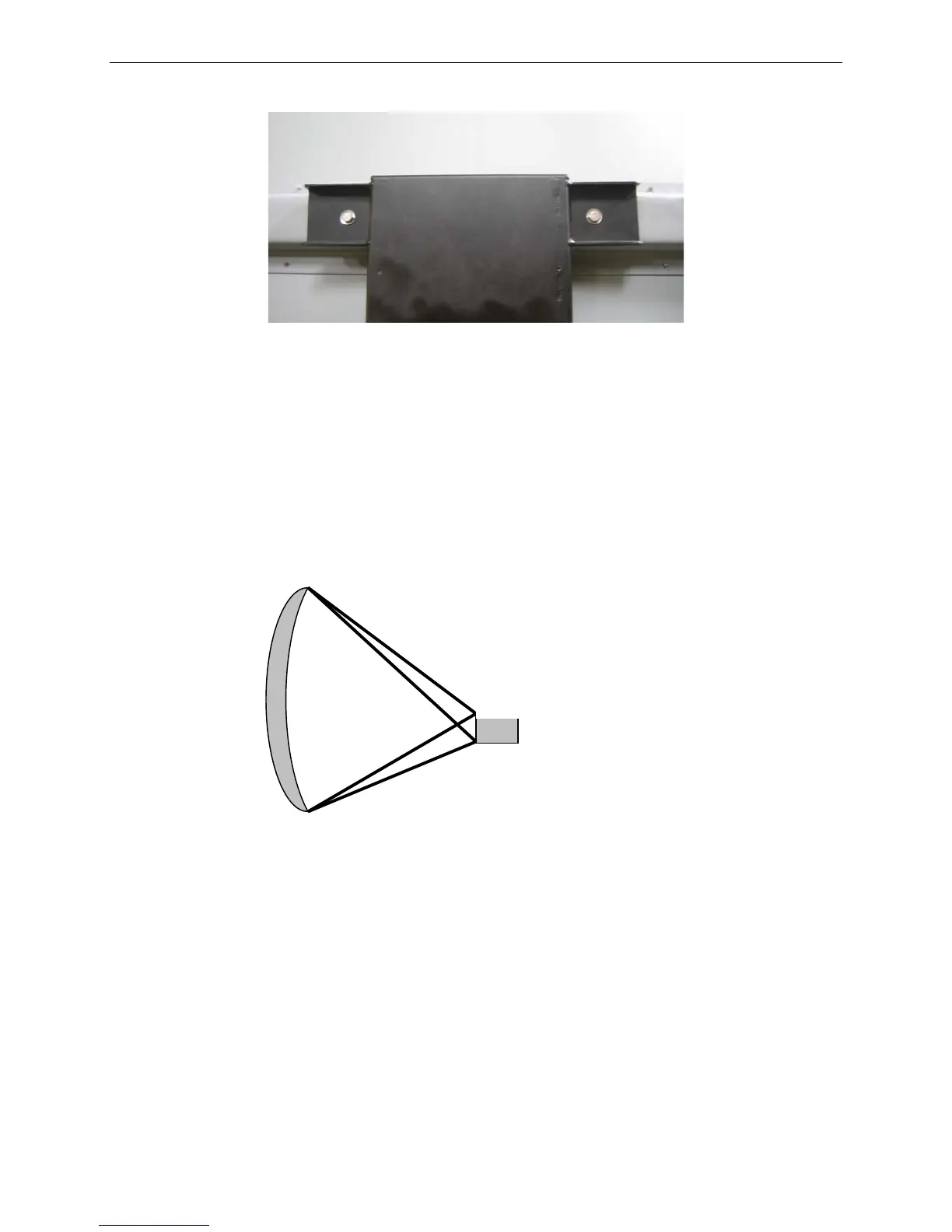
Fig. 38: Reflector Mounting Locations - Close-up
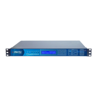
5. Verify Focal Point (ABCD) Geometry. Measure from the outer-most edge on the
top and bottom edge of the reflector. Ensure that dimensions are within ¼ ” of the
values below depending on the type of polarization cage you have installed,
whether it be Ku, X, or C Band.
Ku-Band
A – 40.5”
B – 43.2”
C – 72.9”
D – 70.3”
X-Band
A – 41.3”
B – 43.5”
C – 73.8”
D – 71.2”
C-Band
A – 39.5”
B – 44.1”
C – 73.8”
D – 69.4”
Feed Horn
Reflector