53
Serviceanleitung / Service Manual / / /
Montage der Leiterplatte CPU:
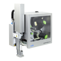
12. Kontaktieren Sie die Steckverbinder (7 bis 10) an der
Unterseite der Leiterplatte CPU.
Nur beim A3 befindet sich der Druckkopf-
Leistungsanschluss (9) an der Leiterplatte CPU, bei
A4, A6 und A8 befindet sich dieser am Netzteil.
13. Schwenken Sie die Leiterplatte nach oben und
befestigen Sie sie
- beim A3 mit vier Schrauben M4x10 (1) und
- bei A4, A6 und A8 mit fünf Schrauben M4x10 (2).
14. Kontaktieren Sie die seitlichen Steckverbinder (11 bis
15).
15. Montieren Sie die Rückwand.
16. Stellen Sie den Stromanschluss und die Schnittstel-
len-Anschlüsse an der Druckerrückseite wieder her.
17. Nehmen Sie bei Bedarf ein Firmware-Update vor.
18. Gleichen Sie die Etikettenlichtschranke gemäß
Abschnitt 2.4.2 ab.
19. Nehmen Sie die notwendigen Einstellungen in der
Druckerkonfiguration vor.
Mounting the PCB CPU:
12. Insert the plugs (7 to 10) into the underside of the
CPU PCB.
Only for A3 the printhead power connector (9) is
located at the PCB CPU, for A4, A6 and A8 it is
located at the power supply.
13. Swivel the PCB upwards and secure it
- for A3 with four screws M4x10 (1) and
- for A4, A6 and A8 with five screws M4x10 (2).
14. Insert the plugs (11 to 15) at the side of the PCB.
15. Refit the rear cover of the printer.
16. Reinstall the power supply connector and the
connectors for the peripheral interface, your optional
interface card inclusive, on the rear of the printer.
17. If necessary carry out a firmware update.
18. Adjust the label edge sensor as described in
section 2.4.2.
19. Perform the needful adjustments in the Printer
Configuration.
7 - Etikettenlichtschranke
8 - Kleinspannungseingang vom Netzteil
9 - Druckkopf-Leistungsanschluss (Nur bei A3)
Bei A4, A6 und A8 befindet sich der Druckkopf-
Leistungsanschluss am Netzteil.
10 - Druckkopf-Logikanschluss
11 - Motor
12 - Kopfverriegelung
13 - USB-Peripherieanschluss
14 - USB-Peripherieanschluss
15 - Bedienfeld
7 - Label edge sensor
8 - Low-voltage input from power pack
9 - Printhead power connector (Only A3)
For A4, A6 and A8 the printhead power connector
is located at the power supply.
10 - Printhead logic connector
11 - Motor
12 - Head lock
13 - USB peripheral interface
14 - USB peripheral interface
15 - Control panel
7 8 9 10
11
12
Bild 32 Anschlüsse an der Leiterplatte CPU
A3 (links) bzw. A4, A6 und A8 (rechts)
Fig. 32 Connectors at the PCB CPU
A3 (left) respectively A4, A6 and A8 (right)
13
14
15
7 8
10
11
12
13
14
15