61
Serviceanleitung / Service Manual / / /
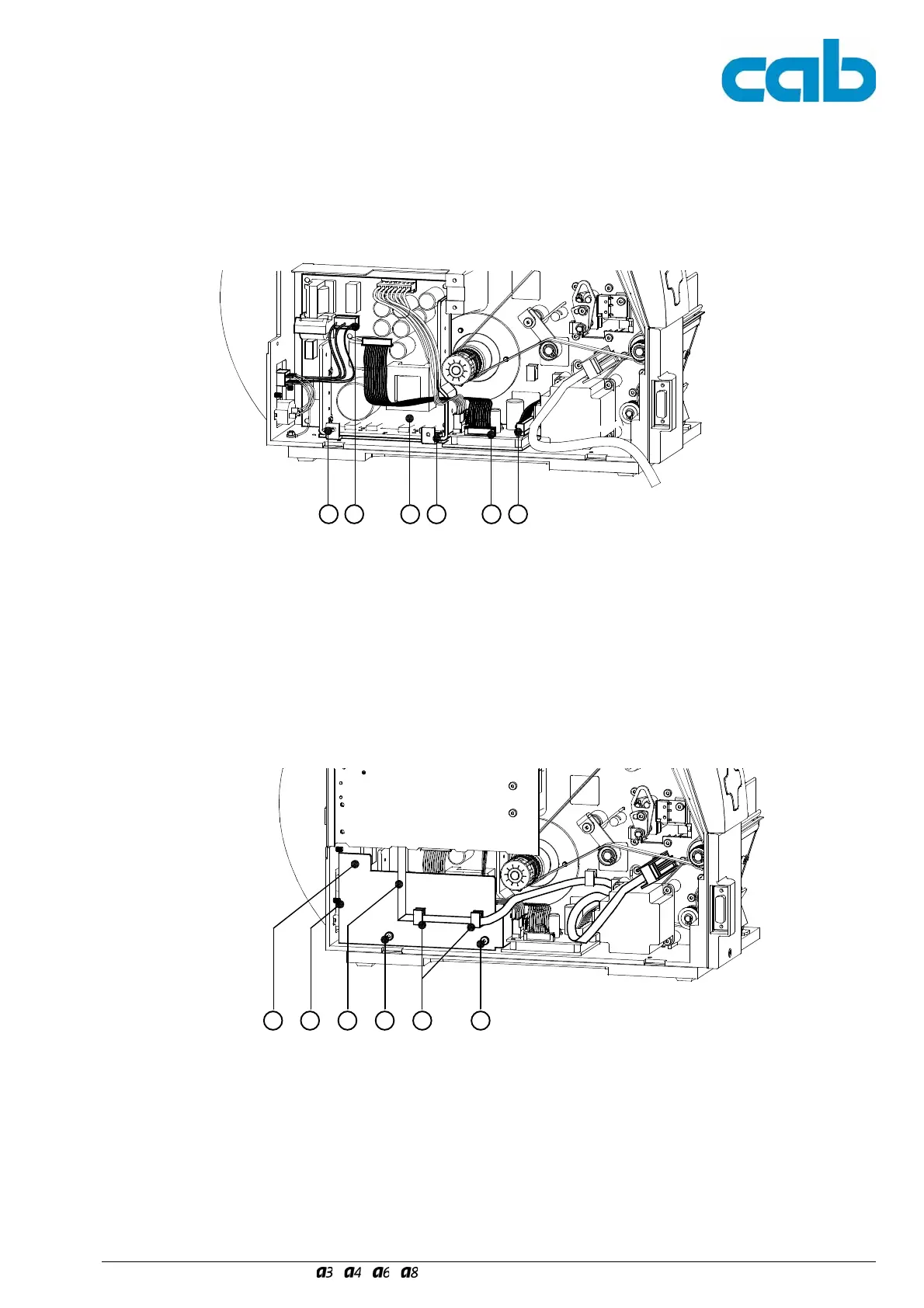
12. Befestigen Sie das neue Netzteil (16), Art.-Nr.
5948800, ausschließlich mit den zwei Schrauben
M4x10 (10) am Boden des Gehäuses.
11. Stecken Sie folgende Stecker auf die Leiterplatte (16)
- Netzeingang (15)
- Leitung Netzteil (17), Art.-Nr. 5948805,
- Druckkopf-Leistungsanschluss (18).
Bild 43 Montage des Netzteilset 2 II Fig. 43 Mounting the Power Supply Set 2 II
15 1716 18
12. Mount the new Power Supply (16), part no. 5948800,
with two screws M4x10 (10) only at the bottom of the
chassis.
11. Put the following connectors into the PCB (16):
- connector (15) of the Power Input Module
- Power Cable (17), part no. 5948805,
- printhead power connector (18).
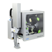
12. Slide the new Cover Plate (19), part no. 5946553,
behind the screw (8). Attach the Cover Plate (19) with
two screws M4x10 (1) to the Power Supply.
13. Slide the flat ribbon cable (2) of the label edge sensor
into the cable holders (20).
14. Remount the PCB CPU as described in section 4.7 .
2 201 1
Bild 44 Montage des Netzteilset 2 III Fig. 44 Mounting the Power Supply Set 2 III
8
12. Schieben Sie das neue Abdeckblech (19), Art.-Nr.
5946553, hinter die Schraube (8) und befestigen Sie
es mit zwei Schrauben M4x10 (1) am Netzteil.
13. Führen Sie die Flachbandleitung (2) der Etikettenlicht-
schranke in die Kabelhalter (20).
14. Montieren Sie die Leiterplatte CPU gemäß
Abschnitt 4.7 .
19
10 10