65
Serviceanleitung / Service Manual / / /
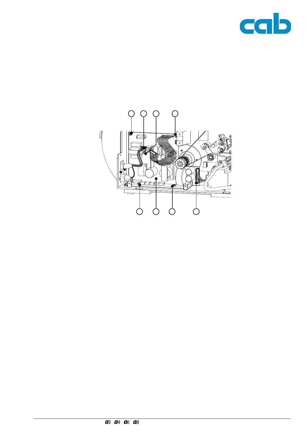
6. Pull the following plugs out of the PCB (8):
- connector (6) of the Power Input Module
- printhead power connector (9).
7. Remove the three screws (5) and the two screws
M4x6 (7) to remove the power unit (8).
Attend on the correct adjustment of the hind insulator
plate.
8. Follow the above steps in the reverse order to fit the
spare power supply.
6. Ziehen Sie folgende Stecker von der Leiterplatte (8):
- Stecker (6) Netzeingang
- Druckkopf-Leistungsanschluss (9).
7. Entfernen Sie die drei Schrauben (5) und die zwei
Schrauben M4x6 (7). Entnehmen Sie das Netzteil (8).
Achten Sie auf eine exakte Ausrichtung der dahinter
befindlichen Isolierplatte.
8. Folgen Sie den Anweisungen in umgekehrter Reihen-
folge, um das Ersatz-Netzteil einzubauen.
7 8 7
5 556
Bild 48 Ausbauen des Netzteils II
Fig. 48 Replacing the Power Supply II
9