16 16
4 Replacing Assembly Units
4.6 Replacing the PCB CPU
Danger!
Risk of death via electric shock!
Before opening the housing cover, disconnect the device from the mains supply and wait at least one
minute until the power supply unit has discharged.
1
2 2
2 2
1. If possible, save the printer conguration to a Compact Flash
card Conguration Manual.
2. Unplug the printer from the electrical outlet.
3. Detach all interface cables from the back of the printer.
4. Remove all memory cards from the slots.
5. Dismount cover.
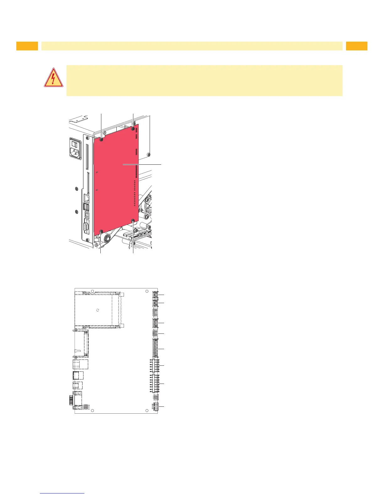
6. Unplug all side plug connections from the CPU (1).
7. Loosen screws (2) and remove CPU (1).
8. Attach the new CPU (1) with four screws (2).
9. Connect all cables to the CPU (1).
10. Mount the rear cover.
11. Restore all interface connections on the back of the printer.
12. Connect the power cable.
13. Update the rmware if necessary.
14. Adjust the label sensor Conguration Manual.
15. Load the printer conguration from the memory card if
possible. Otherwise, set the printer conguration via the
control panel Conguration Manual.
Figure 13 Replacing the CPU
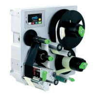
CON02
CON03
CON05
CON07
CON08
CON09
CON11
CON06
CON2 PCB Control Panel
CON3 PCB USB Hub
CON5 Sensors
CON6 Sensors
CON7 Printhead - Signals
CON8 Printhead - Power supply
CON9 Power supply unit
CON11 Main motor
Figure 14 Connectors on the CPU Layout diagram