17
2 Replacing Assembly Units
2.12 Replacing the CPU PCB
Danger!
Danger to life and limb from electric shock!
Disconnect the device from the mains supply before opening the outer casing.
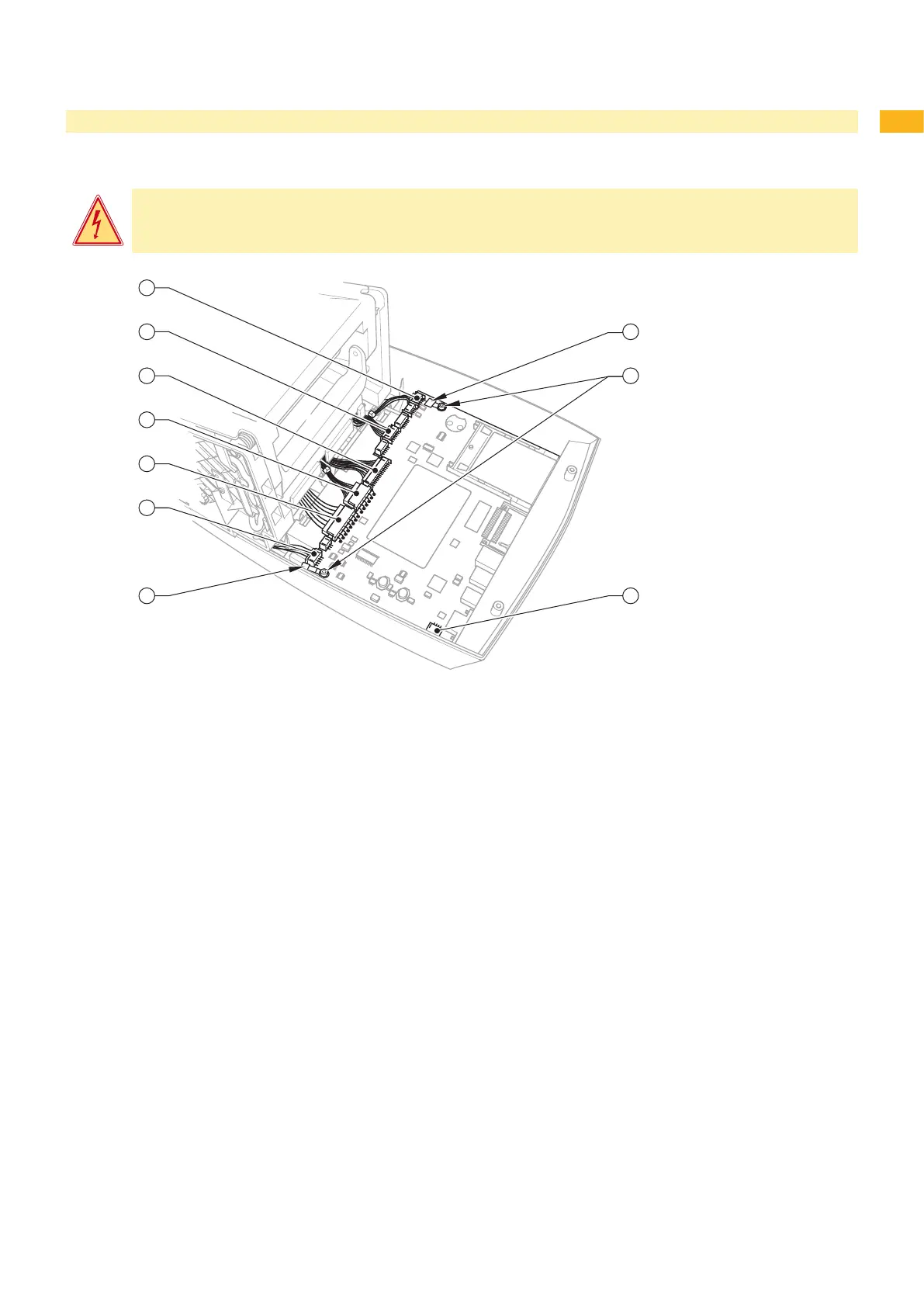
Fig. 11 Replacing the CPU PCB
1 Control panel cable
2 Sensors cable
3 Cable for printhead power supply
4 Printhead signal cable
5 Power unit cable
6 Stepping motor cable
7 Grounding cable
8 Grounding cable power input module
9 Screw
10 Fan cable
Save the printer conguration on a CompactFlash card, the conguration manual.
Pull out all memory modules of their slots.
Remove the outer casing ( 2.5 on page 10).
Disconnect cables (1) to (6) from the CPU PCB.
Loosen both screws (9) and the grounding cables (7, 8).
Disconnect the fan cable (10) and remove the CPU PCB.
Reassemble in the reverse order.
Perform a rmware update as required.
Load the printer conguration from a CompactFlash card, or set it on the control panel, the conguration
manual.
1.
2.
3.
4.
5.
6.
7.
8.