AMETEK Programmable Power
BPS Series User Manual M440077-01 Rev A 38
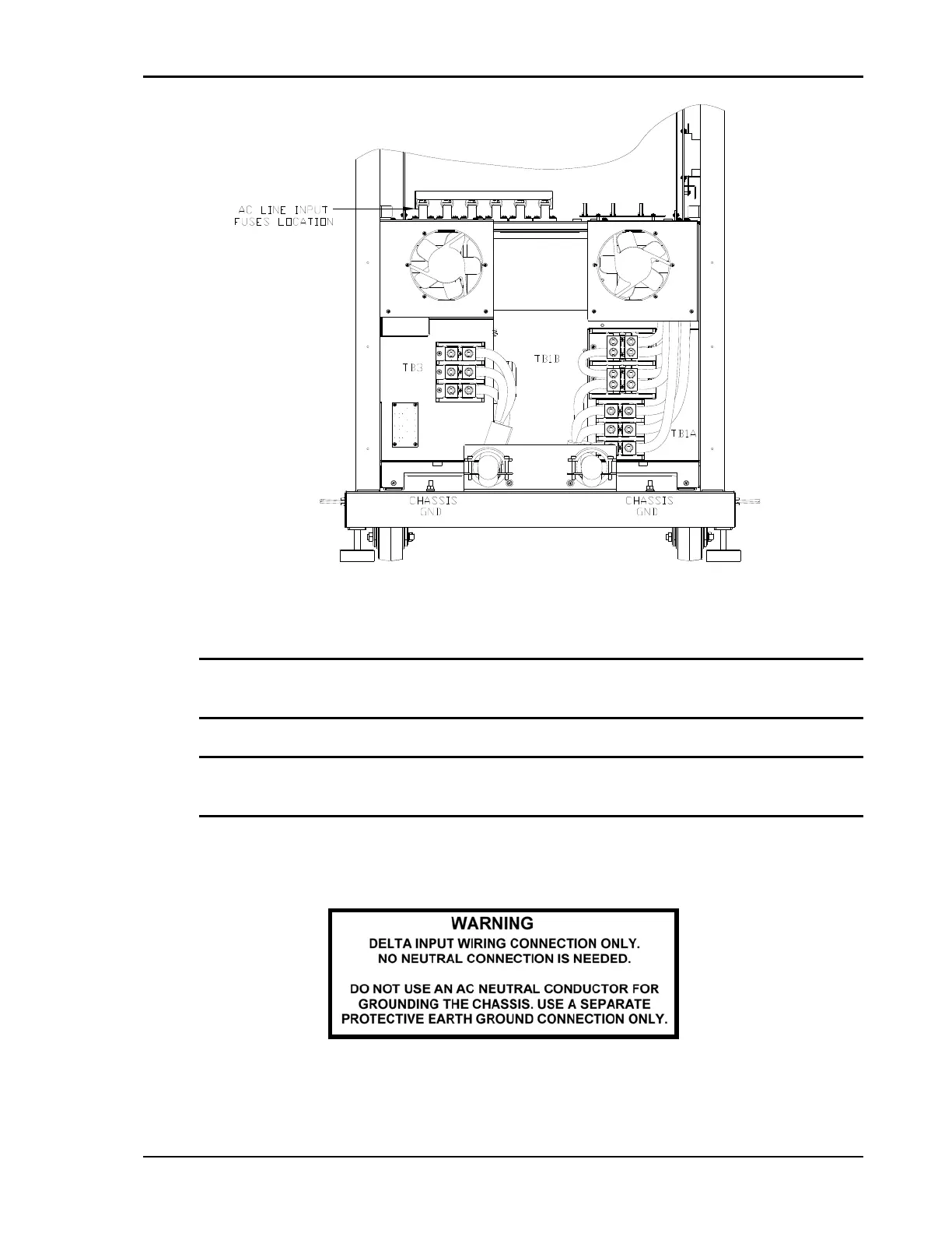
Figure 4-2: Location of BPS75 and BPS90 AC Input Connection Block (TB3) and Chassis Ground Connection
Note: To comply with product safety requirements, EARTH GROUND must be connected to the
chassis of the AC power system using the ground stud located directly below the AC input fuse
block. Use a Green/Yellow ground wire.
Note: DO NOT USE THE NEUTRAL CONNECTION OF A 3 PHASE Y AC POWER
CONNECTION IN PLACE OF A TRUE EARTH GROUND CONNECTION. AC power
system neutrals cannot be used for protective earth ground.
The mains source must have a current rating equal to or greater than the input fuses and the input wiring
must be sized to satisfy the applicable electrical codes. All covers must be re-installed prior to use and
the strain relief provisions located at the rear bottom of the unit must be used to maintain protection
against hazardous conditions.
 Loading...