User Manual AMETEK Programmable Power
BPS Series 49
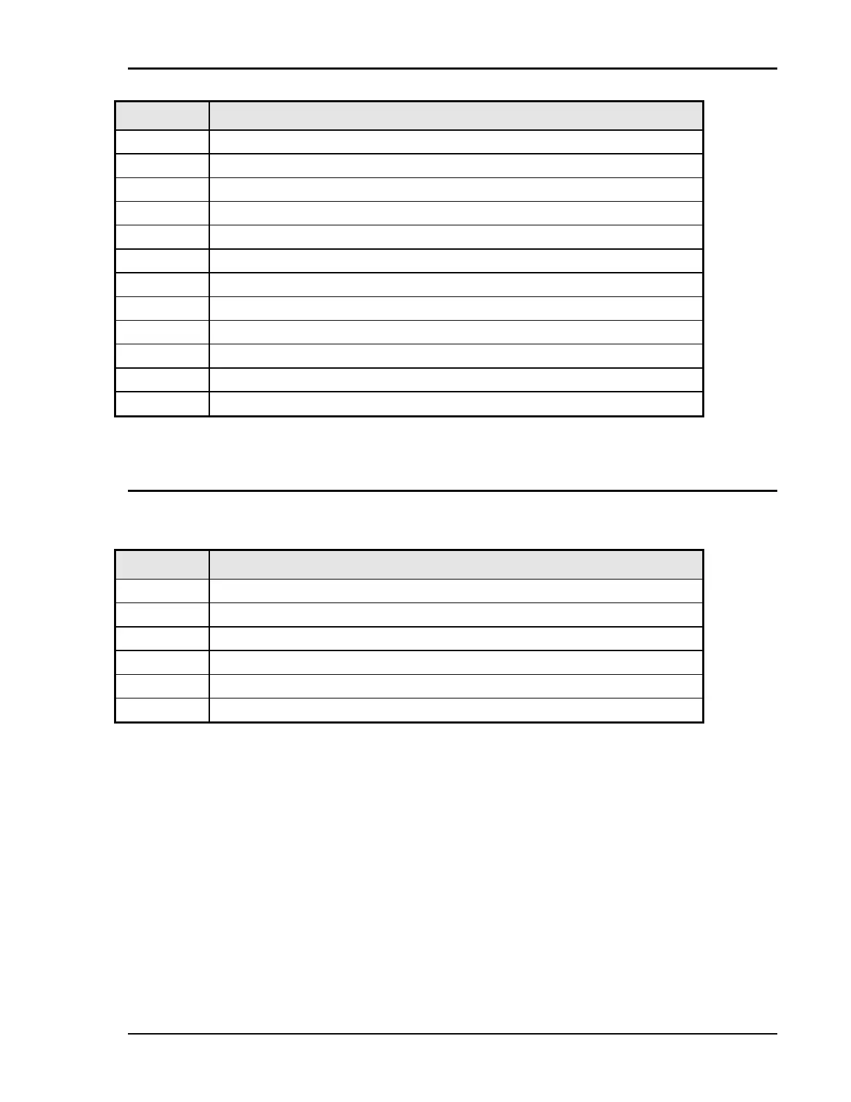
P8 / P9 Description
26 CLA: Current Limit A. Programmed current limit reference for phase A
27 CLC: Current Limit C. Programmed current limit reference for phase C
28 CSB: Current Sum Phase B.
29 N/C
30 FLT B: Amplifier Fault Phase B
31 N/C
32 DC: DC mode control
33 INP OFF: Input power control
34 A ERR HI: Error Signal Phase A, high
35 N/C
36 B ERR LO: Error Signal Phase B, low
37 C ERR HI: Error Signal Phase C, high
Table 4-4: System Interface Connectors
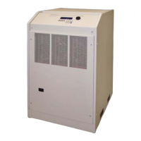
4.7.2 Analog Input Connector
Input screw-terminal strip. Functions are called out on rear panel decal. Table shows connections from left
to right when standing at the rear of the BPS cabinet.
Pin Description
1 RPV HI. INPUT: Analog input for External Modulation
2 RPV Lo. INPUT: return.
3 EXT SYNC HI INPUT: Analog input for external sync mode.
4 EXT SYNC Lo INPUT: return.
5 RI: INPUT: Remote Inhibit. (See paragraph 4.10.)
6 RI: INPUT: return.
Table 4-5: Analog Interface Connector