NC
NA
C
U1
L
N
NC
NA
C
L
N
U2
M
E
F
G
1
2
NA NC
1
2
Page 9 - Manual FB00942-EN - ver. 1 - 11/2017 - © CAME S.p.A. - The contents of this manual are subject to change at any time without prior notice.
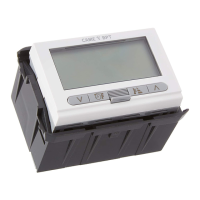
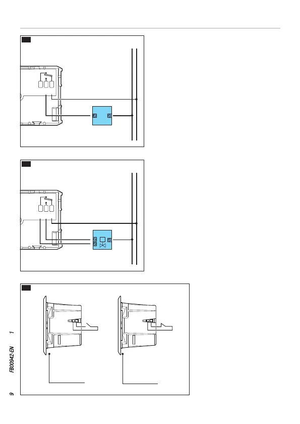
The connections are made depending on
the type of equipment controlled by the
programmable thermostat.
KEY
Mains power supply wires
N = neutral
L = phase
Relay contacts
C = common
NO = normally open contact
NC = normally closed contact
Loads
U1 = burner, circulation pump, solenoid
valve etc.
U2 = motorised valve
Inputs for remote control
1 input
2 input
N.B. For connection, refer to the techni
-
cal documentation of the device to be
controlled.
Wiring
Connection
for remote
activation
Connection
for magnetic
contact
 Loading...