p. 7 - Manual FA01294-EN - 12/2018 - © CAME S.p.A. - The contents of this manual may change, at any time, and without notice. - Original instructions
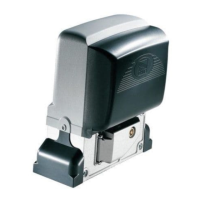
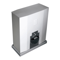
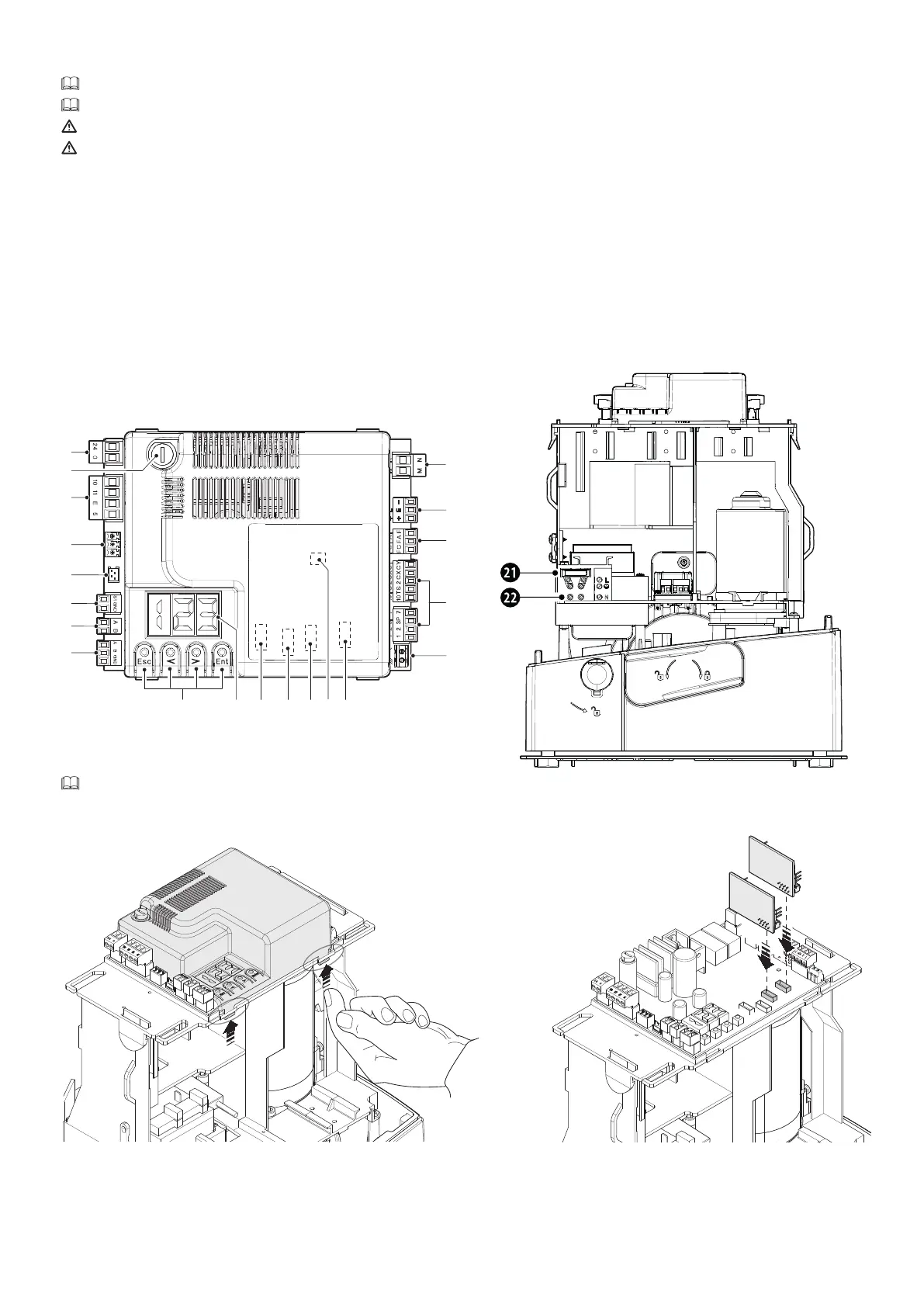
Control board
The functions on the input and output contacts, the time settings and user management, are set and viewed on the display.
All wiring connections are quick-fuse protected.
For the system to work properly, before fitting any plug-in card, you MUST CUT OFF THE MAIN POWER SUPPLY and remove any batteries.
Before working on the control panel, cut off the mains power supply and remove any batteries.
1 - Terminal board for connecting the gearmotor
2 - Terminal board for connecting the Encoder
3 - Terminal board for connecting the limit switches
4 - Terminal board for connecting control and safety devices
5 - Terminal board for connecting the antenna
6 - Snap in connector for radio frequency board (AF)
7 - Memory Roll card connector
8 - Connector for the R700 or R800 decoding card
9 - RSE card connector
10 - RIOCN8WS card connector
11 - Display
12 - Buttons for programming
13 - Terminal board for connecting the combined or CRP function
14 - Terminal board for connecting the selector to the keypad
15 - Terminal board for connecting the transponder selector
16 - Connector for the GSM module
17 - Terminal board for connecting the RGP1 module
18 - Terminal board for connecting the signalling devices
19 - Accessories fuse
20 - Terminal board for power supply to the control board
21 - Line fuse
22 - Power supply terminal board
To insert the snap-in boards into the dedicated connectors, remove the board cover.
R700
R800
AF
 Loading...