p.
5 - Manual code:
FA00095-EN v.
4 - 08/2017 - © Came S.p.A. The contents of this manual may be changed at any time without prior notice.
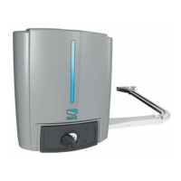
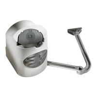
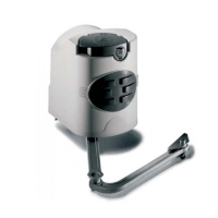
Applicative examples
Fitted with standard jointed transmission-arm. Fitted with the STYLO-BD straight transmission-arm and slide rail.
GENERAL INSTALLATION INDICATIONS
⚠
Only skilled, qualified staff must install this product.
Preliminary checks
⚠
Before beginning, do the following:
• check that the gate structure is sturdy enough, the hinges work efficiently and that there is no friction between the fixed and moving parts;
• if ground stops are not, or cannot be, fitted, use the supplied mechanical stops;
• make sure that the point where the gearmotor is fastened is protected from any impacts and that the anchoring surface is solid enough;
• make sure you have set up a suitable dual pole cut off device along the power supply that is compliant with the installation rules. It should
completely cut off the power supply according to category III surcharge conditions (that is, with minimum contact openings of 3 mm);
• make sure that any connections inside the container (ones that ensure continuity to the protection circuit) are fitted with additional insulation
with respect to those of other electrical parts inside:
set up suitable tubes and conduits for the electric cables to pass through, making sure they are protected from any mechanical damage
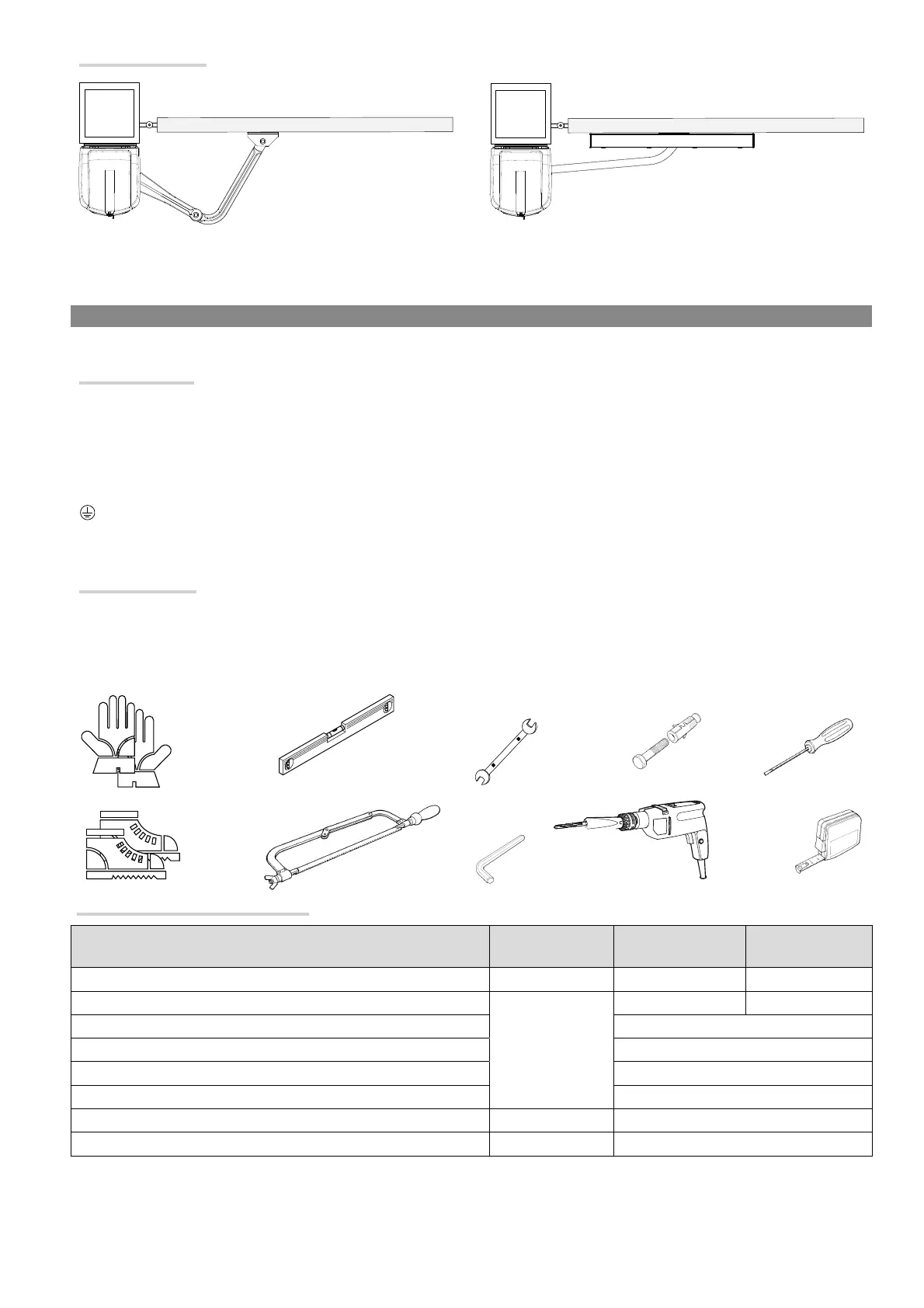
Tools and materials
Make sure you have all the tools and materials you will need for installing in total safety and in compliance with applicable regulations. The figure
shows some of the equipment installers will need.
Cable types and minimum thicknesses
Connection Tipo cavo
Cable length
1 < 15 m
Cable length
15 < 30 m
Control panel power supply 230 V AC H05RN-F 3G x 1,5 mm
2
3G x 2,5 mm
2
Motor/encoder power supply 24 V DC
FROR CEI 20-22
CEI EN
50267-2-1
3 x 1,5 mm
2
3 x 2,5 mm
2
Flashing light 2 x 0,5 mm
2
Photocell transmitters 2 x 0,5 mm
2
Photocell receivers 4 x 0,5 mm
2
Command and safety device 2 x 0,5 mm
2
Antenna the RG58 antenna max 10 m
Came Remote Protocol (CRP) UTP CAT5 max 1000 m
If cable lengths di er from those specifi ed in the table, establish the cable sections depending on the actual power draw of the connected
devices and according to the provisions of regulation CEI EN 60204-1.
For multiple, sequential loads along the same line, the dimensions on the table need to be recalculated according to the actual power draw and
distances. For connecting products that are not contemplated in this manual, see the literature accompanying said products.

 Loading...