p.
7 - Manual code:
FA00095-EN v.
4 - 08/2017 - © Came S.p.A. The contents of this manual may be changed at any time without prior notice.
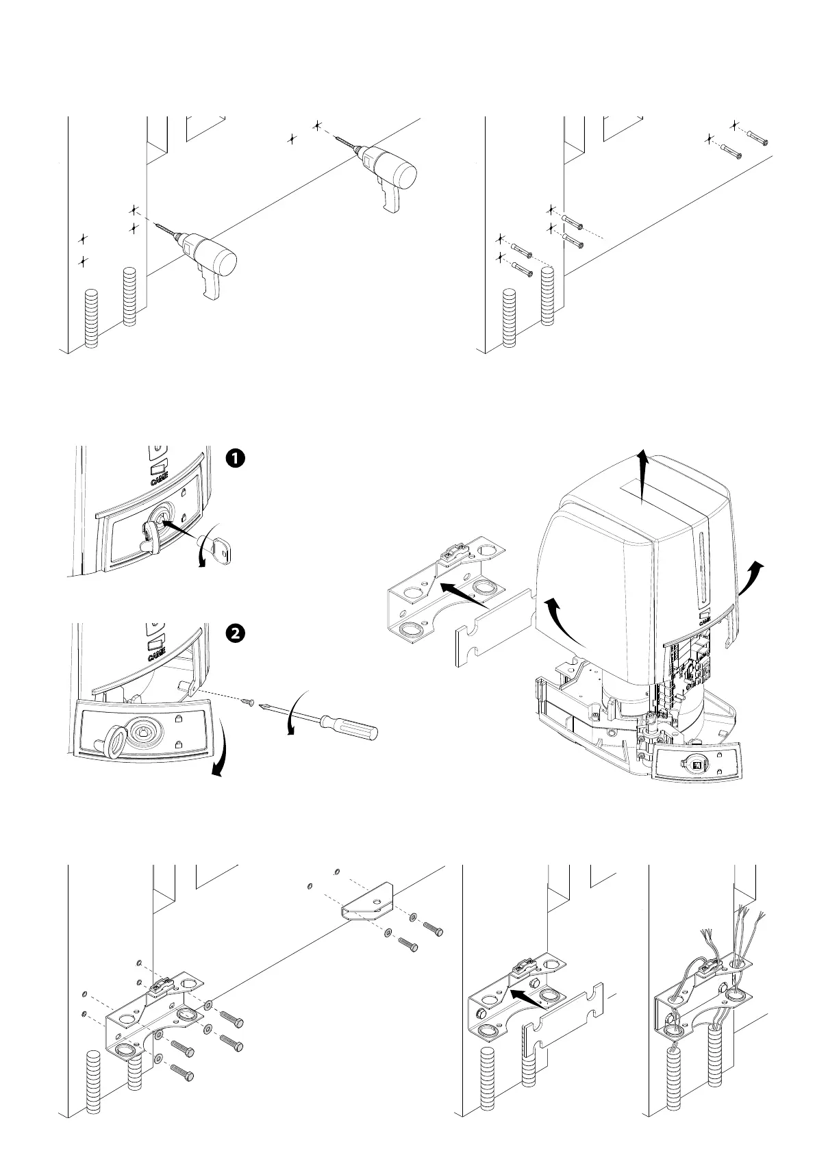
Marked the spots where the gate-post brace and gate brace will be fitted. The center-distances of the holes on the braces are shown in the
Dimensions paragraph.
Drill the anchoring points, fit the dowels or use plugs that will hold fast the screws.
The drawings are mere examples. Installers should carefully choose the most suitable set up according to the type and thickness of the gate
leaf.
Before fitting the operator, remove the casing, as follows: - open the release-hatch protective-cap, fit the trilobe key into the lock and turn it
counterclockwise.
().
- open the hatch door and loosen the screw that fastens the casing to the gearmotor ().
- raise the cove by slightly pulling on its sides and pull out the gate-post brace from the gearmotor ().
Use suitable screws to fasten the brackets.
Fit the rubber shim into the gate-post brace. Lay the electric cables and run them through the cable glands; fasten them using the clamp on the
gate-post brace.
 Loading...