Do you have a question about the CAME FROG and is the answer not in the manual?
Crucial safety warnings, directives, standards, personnel, site, and mechanical safety.
Operational dangers, entrapment risks, and residual risk signage.
Description of FROG-A24/A24E models, intended use, and component identification.
Model technical specifications, usage limitations, and cable selection advice.
Steps for positioning, installing, and securely fastening the gearmotor.
Adjusting mechanical limit switches for gate opening and closing positions.
Wiring instructions for models with and without encoders.
Setting slow-down points for standard and outwards opening.
This document provides a comprehensive installation manual for the CAME FROG-A24 and FROG-A24E swing-gate operators. These devices are designed for automating swing gates in residential and apartment block settings, offering a concealed solution for gate automation. The FROG-A24 is an underground irreversible 24 V gearmotor with an adjustable leaf-stop during closing, while the FROG-A24E adds an encoder to the same specifications. Both models are suitable for swing gates with leaves up to 3.5 meters in length and weighing up to 400 kg.
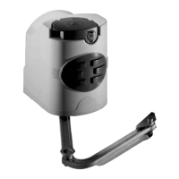
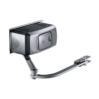
The CAME FROG-A24 and FROG-A24E are electromechanical operators designed to automate the opening and closing of swing gates. The gearmotor is installed underground, making it a discreet solution that does not interfere with the aesthetic appearance of the gate. The operator works by transmitting movement to the gate leaf via a lever system connected to the gearmotor arm.
For the FROG-A24 model, the operator utilizes mechanical limit switches to define the gate's opening and closing travel end points. These limit switches are adjustable, allowing for precise calibration of the gate's movement. The FROG-A24E model, in addition to mechanical limit switches, incorporates an encoder. An encoder provides more precise control over the gate's movement, allowing for advanced features such as obstacle detection and smoother acceleration/deceleration, which contributes to enhanced safety and operational efficiency.
Both operators are irreversible, meaning that once the gate is closed, it remains locked without the need for an additional electric lock, although an electric lock is recommended for optimal closing efficiency, especially for larger gates. The 24 V DC motor ensures safe operation and allows for connection to battery backup systems, ensuring functionality even during power outages. The adjustable leaf-stop during closing helps to manage the gate's final closing position and impact.
The system is designed for heavy-duty service, indicating its robustness and suitability for frequent use. The protection rating of IP67 signifies that the gearmotor is completely protected against dust ingress and can withstand immersion in water up to 1 meter, making it highly durable for outdoor underground installation.
The FROG-A24 and FROG-A24E operators are intended for concealed installation, making them an ideal choice for properties where the visual impact of the automation system needs to be minimized. The underground foundation box houses the gearmotor, protecting it from environmental elements and vandalism.
The installation process involves several key steps, starting with the preliminary operations of installing the foundation box and fastening the release devices. The gearmotor itself is then positioned and fastened over threaded pins within the casing. The manual emphasizes the importance of proper lubrication of the transmission lever for smooth operation.
A critical usage feature is the ability to determine and adjust the travel end points. For both models, this involves manually opening the gate to the desired point and then adjusting the opening limit-switch screw until it touches the foundation box. Similarly, for closing, the adjusting screw of the closing limit-switch point is loosened until it touches the transmission lever. These adjustments ensure that the gate opens and closes to the correct positions without overshooting or impacting the gate structure excessively.
For the FROG-A24 model, the manual also details the establishment of slow-down points using magnetic microswitches. This feature allows the gate to slow down before reaching its final open or closed position, reducing wear and tear on the mechanical components and providing a smoother, quieter operation. This is achieved by giving an opening or closing command and stopping the leaves at approximately 600 mm from the strike plate, then positioning the magnetic microswitches accordingly.
The manual also covers the setup for outwards opening gates, which requires specific adjustments to the gearmotor installation and limit-switch settings. This flexibility allows the operator to be adapted to various gate configurations.
Electrical connections are clearly outlined, differentiating between the gearmotor with encoder (FROG-A24E) and without encoder (FROG-A24). The wiring diagrams specify connections for power supply, encoder cables, and slow-down cables, ensuring proper integration with the control panel. Safety is paramount, with instructions to disconnect mains power and remove batteries before any electrical work.
While the manual primarily focuses on installation, it implicitly highlights several aspects that contribute to the device's maintainability and longevity. The robust construction and IP67 rating mean that the internal components are well-protected from dust and water, reducing the need for frequent cleaning or protection from environmental factors.
The instruction to lubricate the transmission lever during installation suggests that periodic lubrication might be required to ensure smooth and quiet operation over time. This is a common maintenance task for mechanical systems with moving parts.
The adjustability of the limit switches is not only an installation feature but also a maintenance one. If the gate's travel points shift over time due to wear or environmental changes, these adjustments can be easily recalibrated to restore optimal performance.
The inclusion of an encoder in the FROG-A24E model offers advanced diagnostic capabilities. Encoders provide feedback on the gate's position and speed, which can be used by the control panel to detect anomalies or issues, potentially simplifying troubleshooting and maintenance.
The manual's emphasis on using skilled and qualified personnel for all operations, including installation and testing, ensures that the device is set up correctly from the start, minimizing potential issues that would require extensive maintenance later. It also stresses the importance of checking the mechanical condition of the guided part (the gate itself) before installation, as a well-maintained gate will reduce strain on the operator and extend its lifespan.
Finally, the requirement to keep the manual within the technical folder and hand over operating manuals to the end user facilitates future maintenance and troubleshooting. Clear documentation ensures that any necessary adjustments or repairs can be performed efficiently and correctly. The manufacturer's policy of replacing damaged power supply cables only by authorized personnel underscores the importance of professional maintenance for critical components.
| Brand | CAME |
|---|---|
| Model | FROG |
| Category | Gate Opener |
| Language | English |