N
M
PT F FC
FA
p.
- Manual code:
FA01036-EN v.
- 01/2018 - © Came S.p.A. - The manual's contents may be edited at any time without notice.
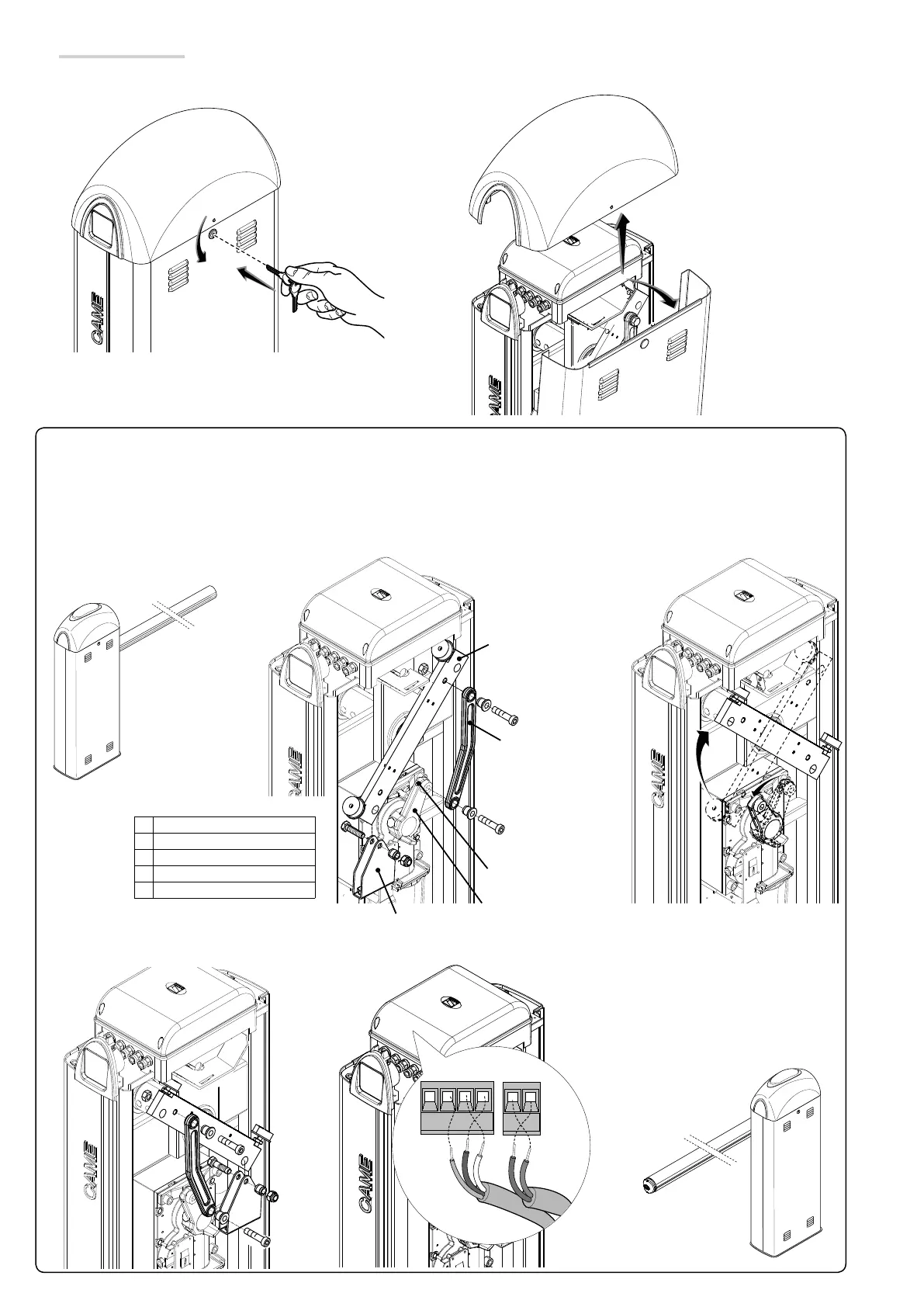
⚠
Warning! The barrier is set up for installing on the left.
When installing on the right, invert the boom's opening direction, as follows:
- loosen the motor arm headless screw, remove the spring attaching bracket and the lever arm transmission rod
;
- turn the lever arm by 90° ;
- fasten the spring attaching bracket to the transmission rod on the part opposite the lever arm and tighten the headless screw ;
- invert the motor phases (M with N) and limit switches (FA with FC) .
Preparing the barrier
Fit the key into the lock and turn it counter clockwise
, lift the dome and remove the inspection hatch .
Lever arm
Transmission rod
Headless screw
Motor arm
Spring attachment bracket
 Loading...


