UNI5931 M8x20
UNI5931 M8x12
UNI5931 M8x20
UNI6954 Ø 2.9x13
p.
- Manual code:
FA01036-EN v.
- 01/2018 - © Came S.p.A. - The manual's contents may be edited at any time without notice.
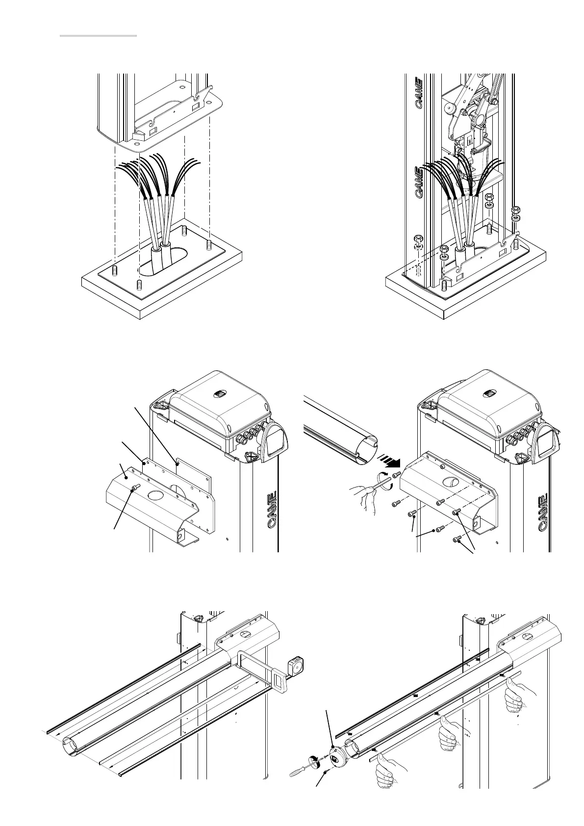
Cut the groove covering profiles to measure and fit them into either side.
Use the screws to fasten the boom endcap.
Motor-shaft plate
Mid plate
Boom-attachment
cover
Boom endcap
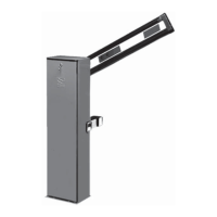
Installing the barrier
The cabinet should be installed with the inspection hatch on the most accessible side to make any adjusting easier.
Place the cabinet onto the anchoring plate and fasten it using nuts and washers.
Assemble the boom-attaching cover, the mid plate and motor-shaft plate with a screw. Leave the screw loose to then facilitate fitting the boom.
Fit the boom into the boom attaching cover and fasten it using the screws.
 Loading...