p.
4 - Manual code:
119PM75 v.
4 10/2014 © CAME S.p.A. - The data and information in this manual may be changed at any time and without notice.
ENGLISH
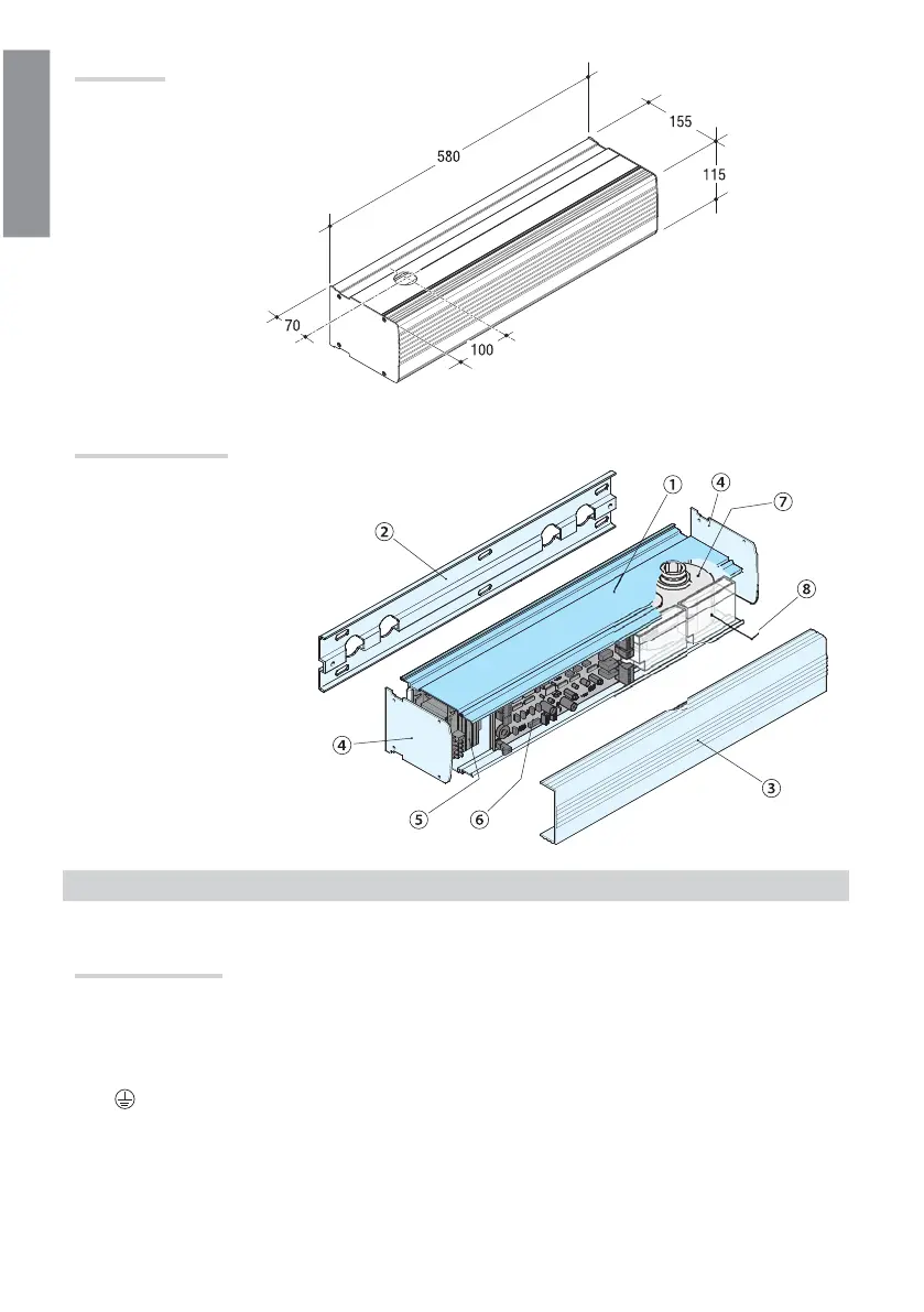
1. Gearmotor case
2. Fastening base
3. Front protective carter
4. Side plates
5. Transformer
6. Control board
7. Gearmotor
8. Batteries (OPTIONAL)
Description of parts
Dimensions
GENERAL INSTRUCTIONS FOR INSTALLING
⚠ Only skilled, qualified staff must install this product.
Preliminary checks
⚠ Before beginning, do the following:
• Connect the control panel to the electric supply line by means of a dual pole cut-off switch with minimum contact
openings of 3 mm, and section the power supply;
• Set up suitable tubes and conduits for the electric cables to pass through, making sure they are protected from any
mechanical damage;
•
Make sure that any connections inside the casing (ones that ensure continuity to the protection circuit) are
fitted with additional insulation with respect to those of other electrical parts inside:
• Make sure the door frame structure is sturdy enough, that the hinges are suitable and that there is no friction
between the moving parts;
• Make sure that at the point where the door is fully opened there is a floor stop to prevent the arm and gearmotor
from overextending.
 Loading...