p. 6 - Manual FA01317-EN - 01/2020 - © CAME S.p.A. - The contents of this manual may be changed at any time and without notice. - Translation of the original instructions
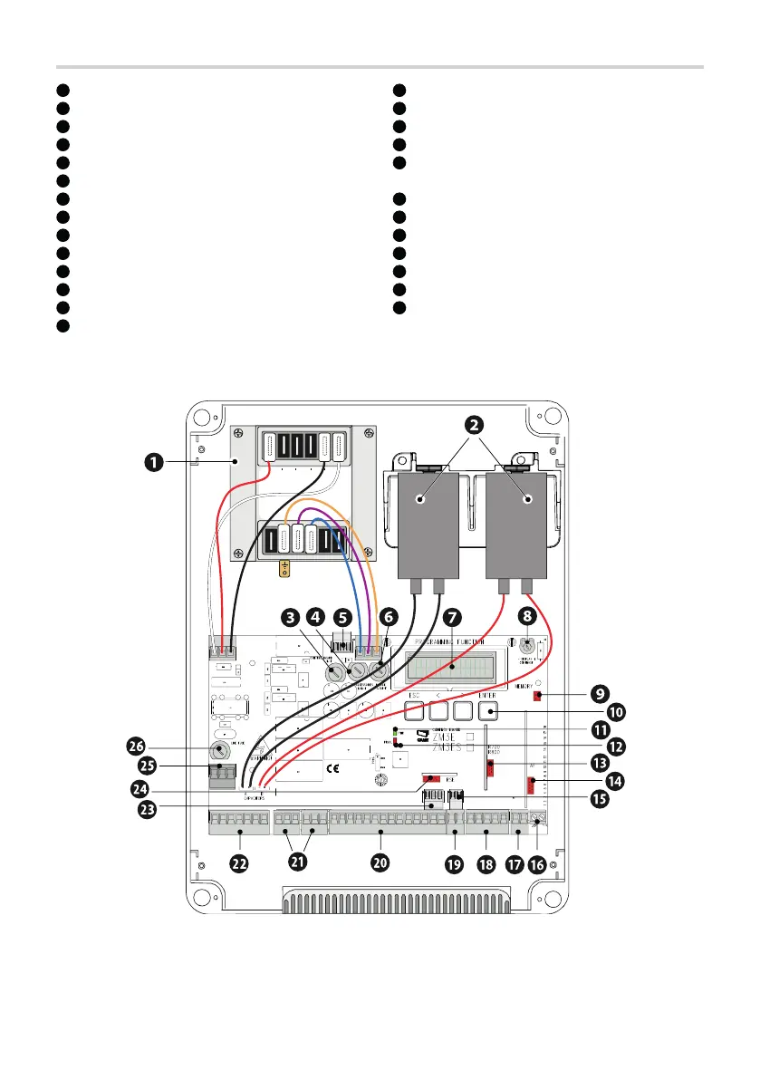
Description of parts
1
Transformer
2
Capacitors *
3
Control board fuse
4
Accessories fuse
5
Terminal board for connecting the RGP1 module
6
Electric-lock fuse
7
Display
8
Trimmer to adjust the display lighting
9
Memory Roll card connector
10
Programming buttons
11
Power LED
12
Programming status warning LED
13
Connector for the R700 or R800 decoding card
14
Connector for plug-in radio frequency card (AF)
10
Terminal board for connecting the keypad selector
16
Terminal board for connecting the antenna
17
Terminal board for B1-B2 output
18
Terminal board for connecting the limit switches
19
Terminal board for connecting the transponder selector
switch
20
Terminal board for connecting control and safety devices
21
Terminal board for connecting the encoder
23
Terminal boards for gearmotors
23
Terminal board for CRP connection
24
RSE card connector
25
Power supply terminal board
26
Line fuse
* Only for 230 V Frog gearmotors.
Use the black cables to connect M1 and the red cables to connect M2.
4
3
2
1