CT-MCL01 l User’s Manual
16
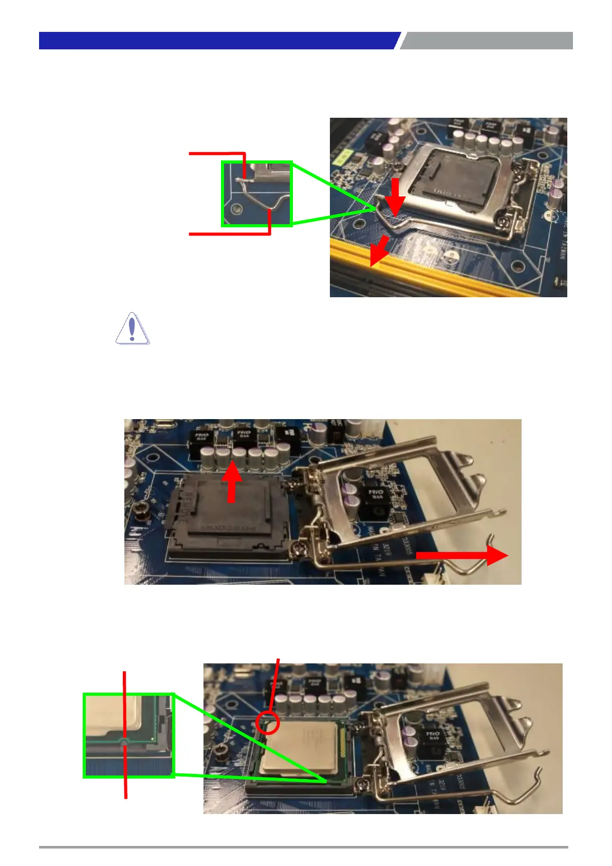
2. Press the load lever with your thumb (A), then move it to the left (B) until it is released from
the retention tab.
3. Lift the Load lever with your thumb and forefinger to around 180° angle (A), then pull the
PnP cap from the CPU socket to remove (B).
4. Position the CPU over the socket, making sure that the gold triangle is on the top-left
corner of the socket then fit the socket alignment key into the CPU notch.
Chapter 1: Product Introductions
 Loading...