PC-D320/PC-D340/FAX-L400 Chapter 3: Assembly and Disassembly
3-9
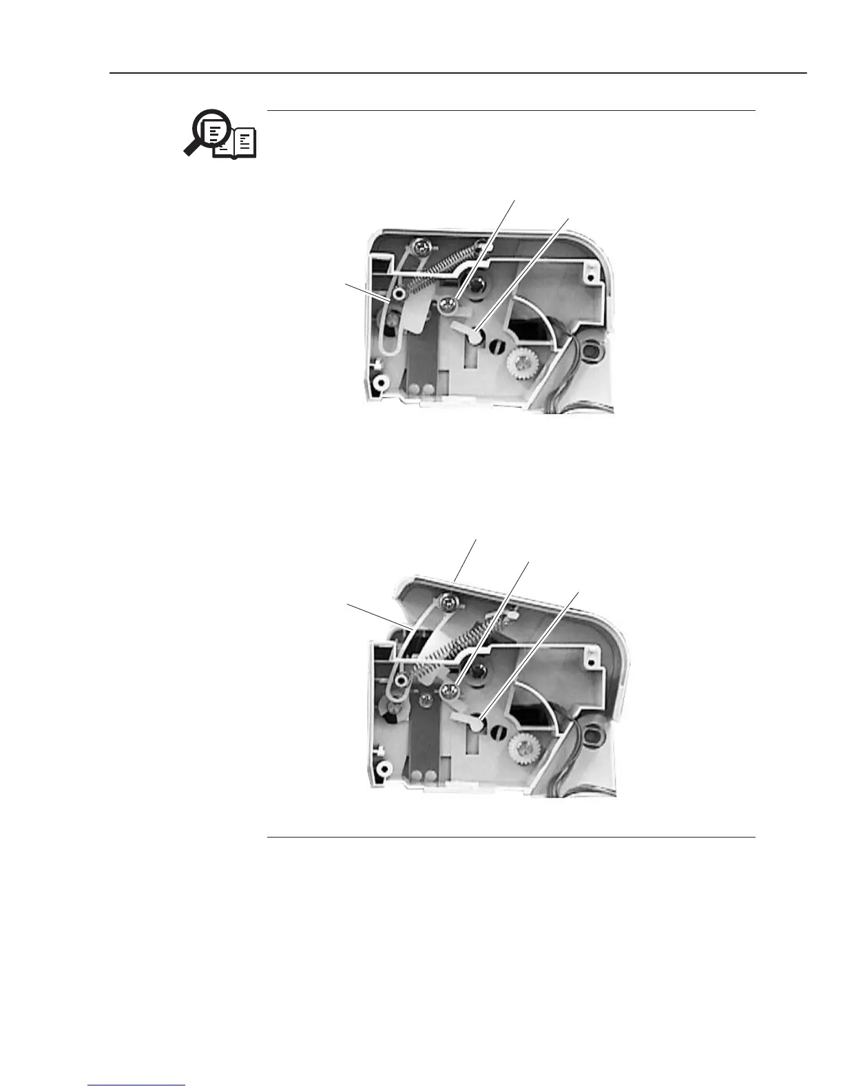
NOTE
Note for Assembling
When attaching the turning lever, be sure the positions of the stopper and the
release lever (See the figure below).
Figure 3-8 Document Feed Section 7
Check to make sure that the stopper lifts up the left side of the turning lever,
and the right side of the turning lever pushes down the release lever.
Figure 3-9 Document Feed Section 8