PC-D320/PC-D340/FAX-L400 Chapter 3: Assembly and Disassembly
3-13
(9) Disconnect the connectors (J504, J505, J506, J509, and J516) on the SCNT board, and
detach the cable from the clamp.
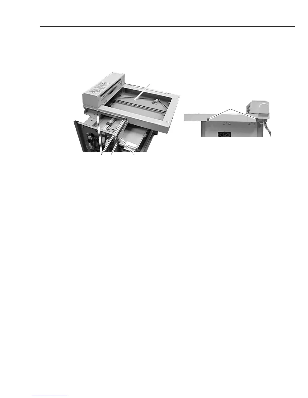
(10) Remove the 4 screws (h), and detach the flat bed ass’y.
(11) Remove the screw (i), and detach the operation panel under cover.
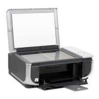
Figure 3-15 Recording Section 5
ih Opration panel under cover
h
Flat bed ass'y
Rear side