PC-D320/PC-D340/FAX-L400 Chapter 3: Assembly and Disassembly
3-14
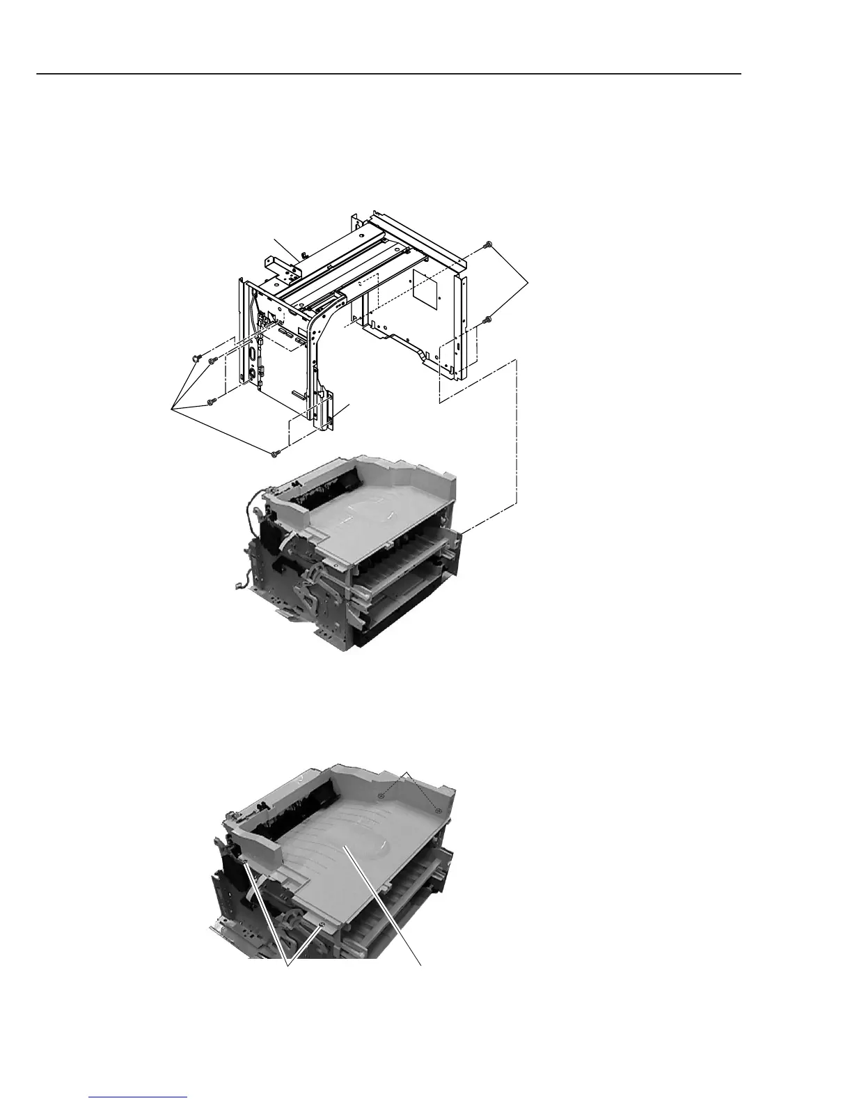
(12) Disconnect the connectors (J507, J508, J511, J514, and J515) on the SCNT board.
(13) Remove the 11 screws (j), and detach the metal chassis unit (For easier removing, free
the fixing boss from its attached place).
Figure 3-16 Recording Section 6
(14) Remove the 4 screws (k), and detach the paper eject frame unit.
Figure 3-17 Recording Section 7
j
Metal chassis unit
Boss
j
Paper eject frame unitk
k (rear side)