PC-D320/PC-D340/FAX-L400 Chapter 3: Assembly and Disassembly
3-17
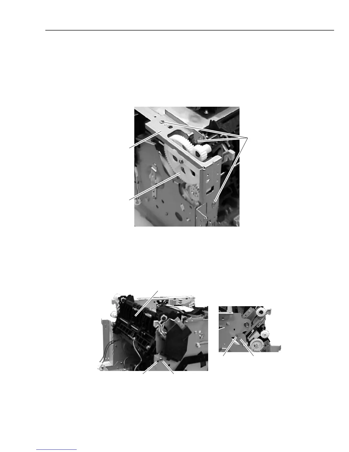
2.1.3 Fixing section
Fixing ass’y
For disassembling the fixing ass’y, follow the steps below after the steps (1)~(14) of 2.1.2
Recording Section: Removing the Separation Pad.
(15) Remove the 3 screws (l), and detach the plate.
(16) Remove the gear (m).
Figure 3-22 Fixing Section 1
(17) Disconnect the connectors (J102, J206 and J210) on the ECNT board, and disconnect
the connector of the cable between the J305 on the ECNT board and the fixing ass’y.
(18) Remove the 2 screws (n); remove the fixing ass’y by shifting to the upper left while
detaching the bosses on the both sides of the fixing ass’y.
Figure 3-23 Fixing Section 2
Plate
l
m
Fixing ass'y
Rear side
Boss n
n Boss