11
Grease Duct and Chimney Joint Assembly
All grease ducts are to be liquid tight per NFPA 96. Model 2R Type HT chimney used in positive pressure
applications must be liquid tight per UL103 and UL103HT listing. When a chimney system is used in a
positive pressure application, it must be fitted with an internal joint collar and sealed as shown in Figure 3
(positive pressure only). When a chimney system is used in a negative or neutral pressure application, it
does not need to be sealed per the listing report; although, sealing the system is recommended for
commercial cooking appliances where grease is present.
1. Fill the V-band with 3M Fire Barrier 2000+ Silicone. The bead should be continuous. See Table 2 for
the number of tubes per joint. For neutral and negative chimney or grease duct applications, proceed
to step 4.
2. For positive pressure chimney applications: Apply a 1/4” wide continuous bead of 3M Fire Barrier
2000+ Silicone around the formed bead on the internal joint collar. Push down into the chimney section
being assembled.
3. For positive pressure chimney applications: The internal joint collar should be pushed down into the
chimney section until the bead sits on the chimney flange.
4. Place the loose V-band over the duct flange. Apply a continuous bead of 2000+ Silicone 1/4” wide to
the flange that will be joined.
5. Join the two flanged ends of the inner duct sections together and rotate slightly to ensure complete
coverage of sealant on flanges.
6. For horizontal duct runs, the V-band hardware should be located on the top side of the duct and
orientated between the 3 and 9 o’clock position on the duct.
7. NEVER install the V-band with hardware orientated on the bottom side of the duct on horizontal runs.
8. Install the V-band around the duct flanges making sure the flanges are located within the V-band. Tap
the outside of the V-band while tightening V-band hardware to make sure the flanges are aligned and
have been pulled together. Secure the 1/4”-20 hardware between 40-60 in-lbs. Smooth out any
excess sealant from inside of the duct surface.
9. Insulation must be minimum of 4-1/2” wide, and the same type and number of layers as the base duct.
Tightly pack and completely fill all voids between the inner duct and the outer shell.
10. Install the double V-band ensuring the outer shell flanges are positively engaged in the V-bands before
tightening the 1/4”-20 hardware between 40-60 in-lbs. The double V-band can be sealed using 3M
Fire Barrier 2000+ Silicone when being installed outside.
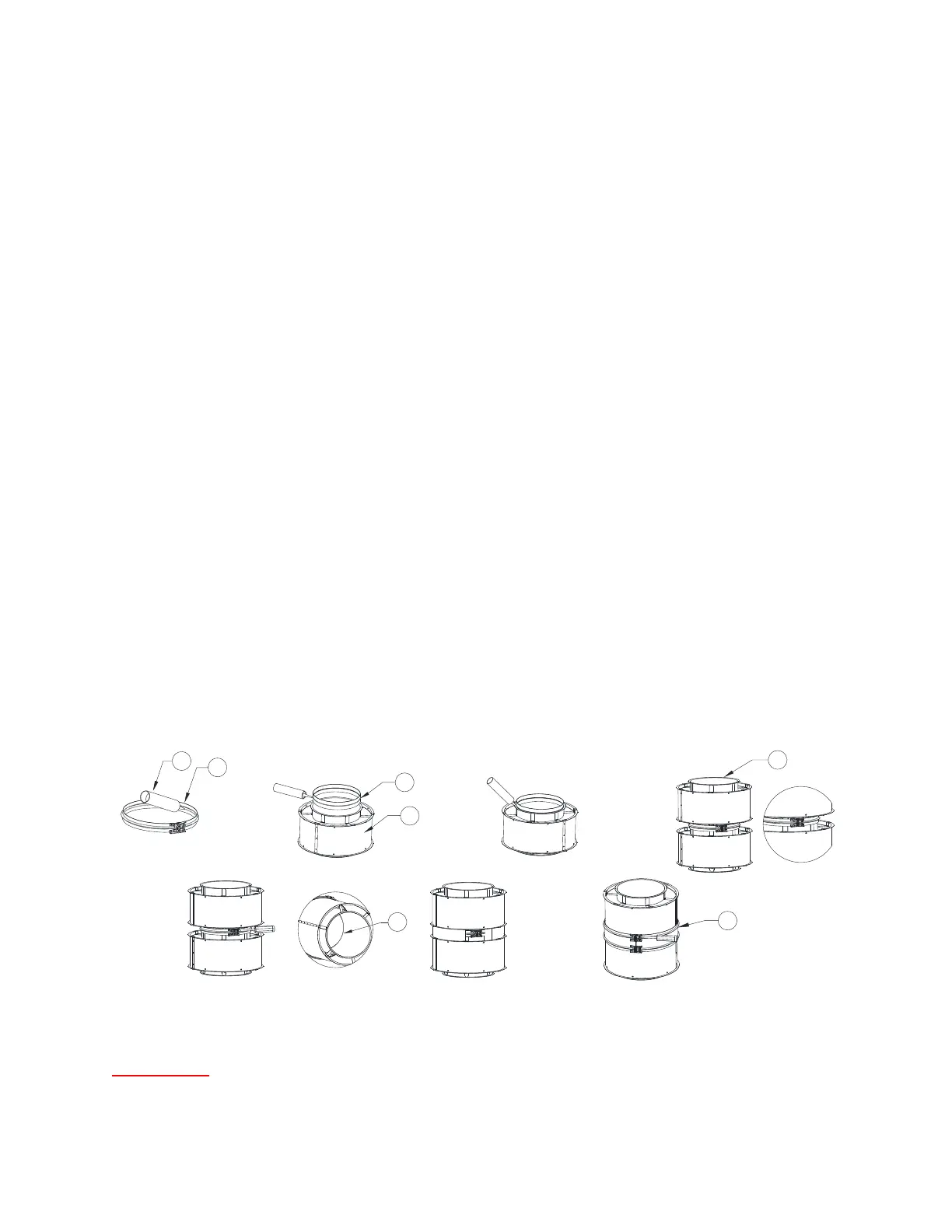
Figure 3 - Duct and Chimney Joint Assembly
IMPORTANT:
THE HARDWARE USED TO ASSEMBLE THIS DUCTWORK/CHIMNEY IS
SPECIFICALLY DESIGNED FOR THIS APPLICATION. NO SUBSTITUTE HARDWARE IS ALLOWED.
ALL REPLACEMENT HARDWARE MUST BE PURCHASED FROM THE FACTORY.
1. 3M Fire Barrier Silicone
2. V-band
3. Internal Joint Collar
(Positive Pressure
Chimney)
4. First Duct Section
5. Second Duct Section
6. Double V-band