29
Double Wall Vertical Support (Wood, Steel, Concrete)
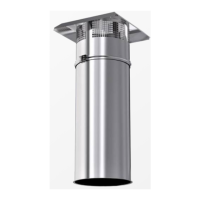
The V-band will sit on top of the flat support plates after the wall support kit installation is complete.
1. Verify wall construction and hardware kit.
• For wood wall construction, the wall must be constructed of 2” x 4” wooden studs with a maximum
spacing of 24” on center and covered with 5/8” gypsum. Use hardware kit DWVESU-HARDWARE-W.
• For steel stud wall construction, the wall must be constructed of 2” x 4” 25 gauge (minimum) with a
maximum spacing of 24” on center and covered with 5/8” gypsum. Use hardware kit DWVESU-
HARDWARE-S.
• For concrete/masonry construction, use hardware kit DWVESU-HARDWARE-CM.
2. The wall support plate has specific holes that locate the side plates so that when installed, they will
match the outer shell diameter. Measure the shell diameter, then measure from the wall plate center
holes to the radius of the opening to locate the first side plate. Refer to Figure 19 for wood/steel
installation details. Refer to Figure 20 for concrete/masonry installation details.
Example: If the shell being installed has a 30” outside diameter, measure from the center of the wall
plate 15”. This will locate the inside of the side plate on the wall plate. Side support plate mounting
holes should be on the outside.
3. Once the first wall support plate is located, use the 7/8” holes that are 24” on center from the side plate
mounting holes to secure the first support plate. In some cases the mounting holes may have to be
drilled to align with studs.
4. Follow the instructions above and mount the second wall support plate. Measurement will be 44” from
the top of the first wall support to the bottom of the second wall support.
NOTE: For steel studs, alternate self-drilling screws and toggle bolts when installing side plates
into stud locations.
5. Install one of the side support plates. Measure from the center of the wall support plate to locate the
first side support plate. Measure 24” from the hardware installed in step 3. Secure wall support plates
to the wall.
6. Measure from the center and install the second side plate.
7. Repeat the above process so that both wall supports and side plates are installed and secure.
8. Install the rear flat support plate using nuts and bolts. Mount the shell so the V-band is above the flat
support plates. Secure by installing the front flat support plate. The V-band should be sitting on top of
the flat plate. A cutout is provided in the flat plate, align the V-band bracket with the cutout so it does
not interfere with the top of the plate.
9. Use self-drilling screws to secure the side support left and right plates to the outer duct shell. Use the
guide holes to locate the shell center and fill all holes at the center, center left and center right.