8
Clearances
In all buildings more than one story in height and in buildings where the roof/ceiling assembly is required to
have a fire resistance rating, the duct must be enclosed in a continuous enclosure from the lowest fire-
rated ceiling or floor above the hood, through any concealed spaces, to or through the roof to maintain the
integrity of the fire separations required by the applicable building code provisions. If the building is less
than 4 stories in height, the enclosure shall have a fire resistance rating of not less than 1 hour. If the
building is 4 stories or more in height, the enclosure shall have a fire resistance rating of not less than 2
hours. Single wall grease duct is primarily intended for use in non-combustible surroundings. When
installed in an open room where an enclosure is not required, double wall grease duct or chimney systems
may be located near combustible material to reduce clearance in accordance with Table 1. When
combining double wall and single wall grease duct for the purpose of clearance reduction, a Double Wall
End Cap Assembly is required.
The information in Table 1 represents air space, in inches, to surroundings.
Refer to the latest edition of NFPA 96, Chapter 3 Definitions. This chapter explains the definitions
on combustible, non-combustible and limited combustible material.
(1)
DW - 2R: 3/4” clearance to combustibles from the surface of the duct outer shell; zero inch clearance
from combustibles from the tip of the outer V-band.
(2)
DW - 2R: 1” clearance to combustibles from the surface of the duct outer shell; zero inch clearance from
combustibles from the tip of the outer V-band.
(3)
DW - 2R TYPE HT: unenclosed, 2” clearance to combustibles from the surface of the chimney outer
shell.
(4)
DW - 3R: 3/4” clearance to combustibles from the surface of the duct outer shell; zero inch clearance
from combustibles from the tip of the outer V-band.
NOTE: Double wall duct systems with reduced clearance “R” have been tested using condition B –
installed within non-ventilated unenclosed combustible enclosure. See Figure 1 for representation
of reduced clearance note, the V-band may be in contact with a combustible surface.
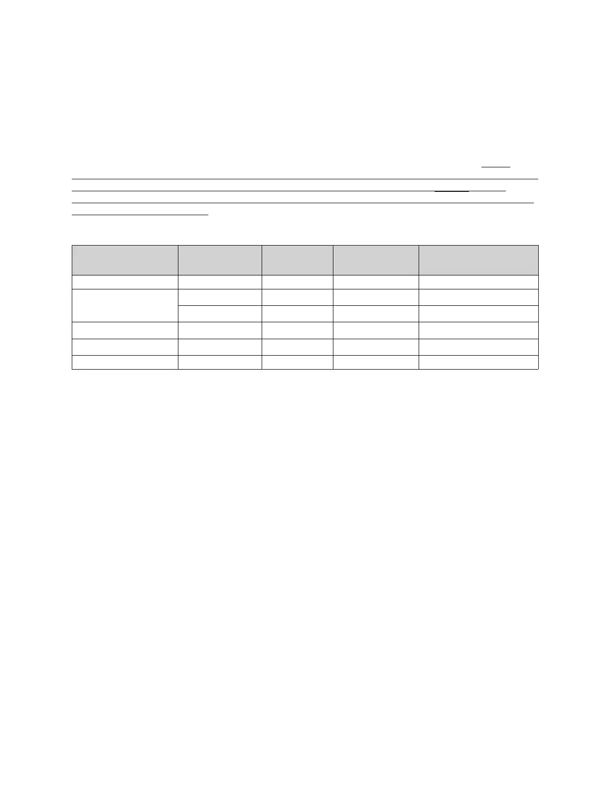
Table 1 - Grease Duct and Building Heating Appliance Chimney Clearances
Duct Model
Inner Diameter
(ID)
Outside
Diameter
Clearance to
Combustibles
Clearance to
Non-Combustibles
DW 8”-36” = ID 18” 0”
DW - 2R
8”-16” ID + 4
3/4”
(1)
0”
18” ID + 4
1”
(2)
0”
DW - 2R TYPE HT 8”-16” ID + 4
2”
(3)
0”
DW - 3R 8”-24” ID + 6
3/4”
(4)
0”
DW - 3Z 8”-36” ID + 6 0” 0”