23
Prevention of Grease Accumulation in Horizontal Grease Duct
In some areas the local authority will require horizontal duct runs to be sloped. The duct referenced in this
manual is listed, 1/16” per foot slope for horizontal runs less than 75 feet. For installations with horizontal
runs greater than 75 feet, the duct referenced in this manual is listed, 3/16” per foot slope. In such cases, a
short “Slope Transition” section is available from the factory. For correct installation, two slope transitions
are generally required - one at the beginning and end of the horizontal duct run. Consult with local code
authorities if unsure about local requirements. Offset collars have been designed to meet the above
specification. The collar is used in conjunction with other accessories such as tees and elbows to maintain
the above listed slope in horizontal duct runs. The “V” band hardware should be located on the top side of
the duct and be orientated between the 3 and 9 o’clock position on the duct. Never install the V-band with
the hardware orientated on the bottom side of the duct on horizontal runs.
Alignment & Bracing of Grease Duct
The grease duct has characteristics of a continuous stainless steel pipe and will expand and contract along
its entire length with changes in temperature. For this reason, conventional methods of attaching guides
and braces to the outer wall of the grease duct cannot be used. Correctly installed support rings, saddles
and wall guide assemblies will serve to keep the duct aligned, provide for adequate resistance to lateral
loads and allow the free axial expansion and contraction movement. A simplified rule for duct expansion is
that the axial growth will be approximately 1 inch per 100 feet of pipe length for each 100 degrees
Fahrenheit the exhaust vapor temperature is above the surrounding air temperature.
Double Wall Horizontal Support and Support Spacing
Horizontal duct runs are supported using 2” x 2” x 1/8” angle, Unistrut and saddle combination, or Unistrut
only. Refer to Table 5 for horizontal support spacing. When cutting the angle or Unistrut to length, there
must be a minimum of 2” on either side of the duct shell to allow for rod attachment. Once the angle has
been cut to length it is suspended using 1/2” threaded rod (minimum). Appropriately sized holes are drilled/
punched in either end of the angle. The 1/2” threaded rod is secured to the angle or Unistrut using 1/2”
grade 5 hex nuts and 1/2” hardened washers, see Figure 15.
NOTE: Double hex nuts are used as locking nuts to make sure hardware does not come loose over
time.
IMPORTANT:
HORIZONTAL SUPPORTS REFERED TO IN THIS MANUAL ARE REQUIRED.
SUPPORTS BY OTHERS MUST BE APPROVED BY THE MANUFACTURER AND AHJ, GREASE
DUCT ONLY. CHIMNEY SYSTEMS MUST USE THE SUPPORTS LISTED IN THE MANUAL,
SUPPORTS BY OTHER ARE NOT ALLOWED. SUPPORT SPACING MUST BE AS STATED IN THIS
MANUAL.
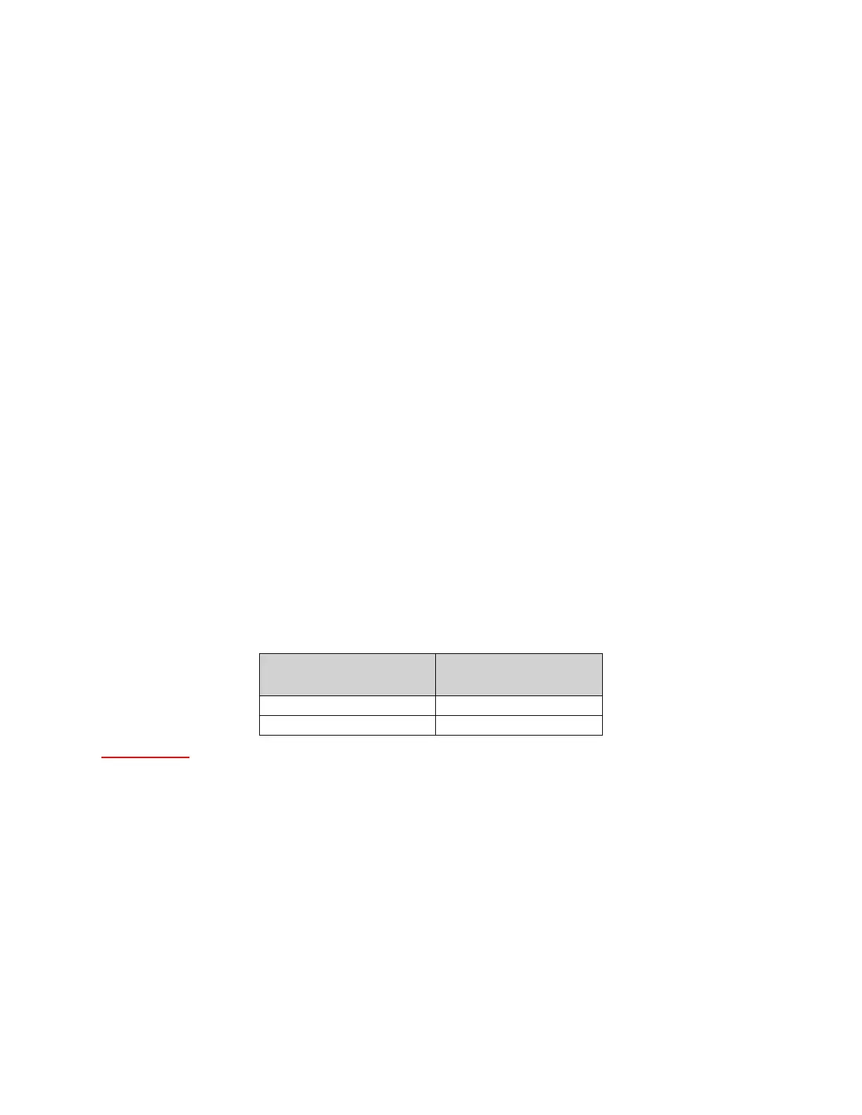
Table 5 - Double Wall Horizontal Support Spacing
Diameter (Inches)
Horizontal Support
Spacing (Feet)
8”, 10”, 12”, 14”, 16” 7’
18”, 20”, 22”, 24”, 30”, 36” 5’