41
Floor and Ceiling Fire Stop Installation
1. Cut an opening in the floor/ceiling that is a minimum of 2” and maximum of 3” larger than the outside
diameter of the duct being installed, refer to Table 8.
2. The grease duct can be installed eccentrically or concentrically within the opening. The distance from
the outside of the grease duct to the periphery of the opening cannot exceed 2”. The maximum annular
distance allowed is 2”, refer to Figure 26.
3. Apply a continuous 1/2” bead of STI Triple S intumescent around the fire plates. The fire plates are
designed to fit around the duct and overlap by 1”.
4. The fire plates are installed on the bottom side of the floor/ceiling. Push the plates up to the floor/
ceiling so the intumescent seals the plates against the floor/ceiling. Then secure using 1/4”-20 x 1-1/2”
long concrete fasteners where the plates overlap, secure using 1/4”-20 x 1” sheet metal screws.
5. Seal the topside using the intumescent seal around the duct and fire plates. Seal the edge of the
opening to the fire plates.
6. Fill the cavity using four layers of insulation, make sure that all voids are filled. The insulation is fully
compressed into the opening until it is 3/4” from the top of the opening.
7. Cover the compressed insulation with intumescent. Continue until the intumescent is level with the top
of the opening. The intumescent should overlap on to the floor/ceiling, ensuring there are no gaps
between the edges of the opening or the duct outer shell.
8. Wrap one layer of 1” x 12” provided insulation around the base of the duct and enclose with the half
enclosure bands. The insulation and bands should be touching the intumescent, do not disturb or
compromise the intumescent when installing. The enclosure bands are assembled using 1/4”-20 x 3/4”
hardware.
9. Install the vertical fire stop support; ensuring the full support ring is installed under the double V-band.
Once in place, the legs are secured to the floor/ceiling using appropriate type and size fasteners.
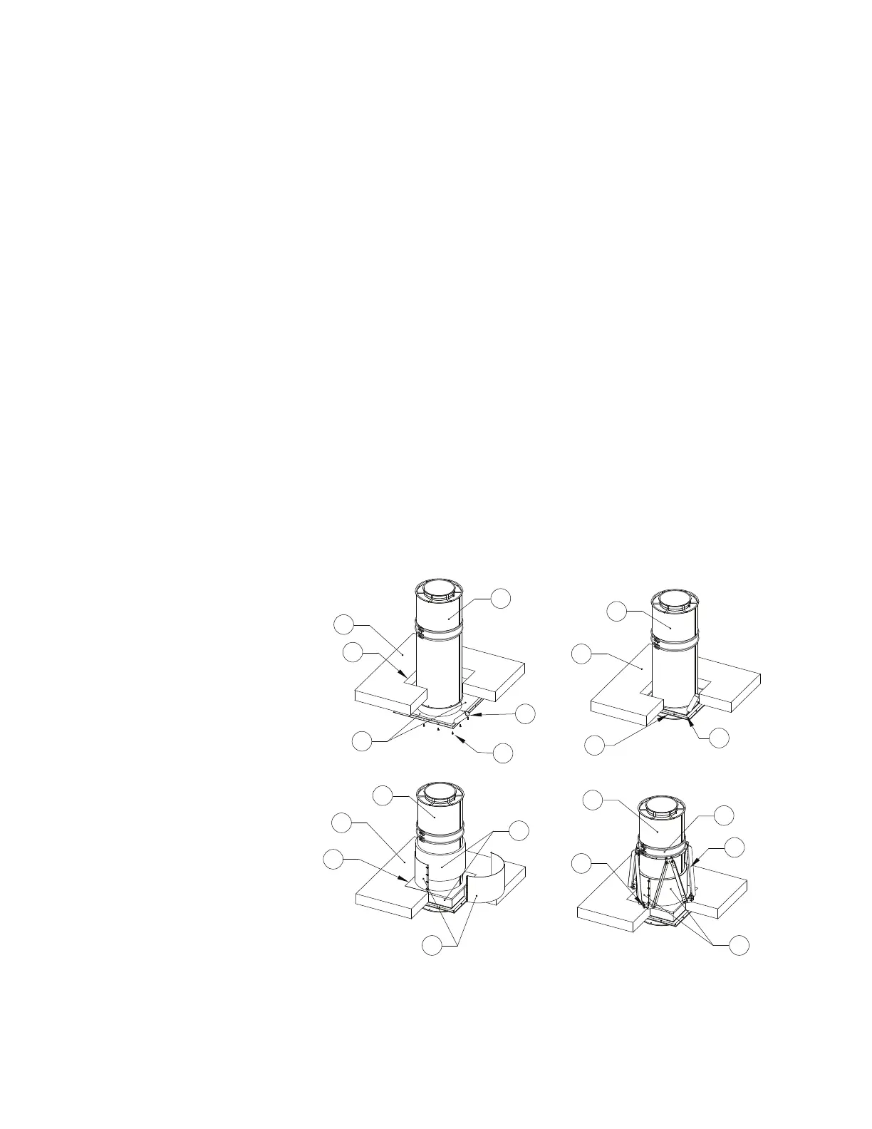
Figure 29 - Floor and Ceiling Fire Stop Installation
1. Top Side
2. Duct Section
3. Intumescent Sealant
4. Concrete Screws
5. Fire Plates
6. Fire Plate - Shown secured
to substrate
7. Insulation
8. Half Closure Bands
9. Double V-band
10. Vertical Support
11. Half Closure Bands - Shown
secured
12. Concrete Anchors
A. Floor Opening, refer to
Table 8.