20
Access Door (Tee Cap) Assembly
Access doors (tee caps) are available 8” to 36”. They work in conjunction with the manifold tee as shown
on “Manifold Tee” on page 19. The tee joint connection is the same as the joint assembly method, refer
to “Grease Duct and Chimney Joint Assembly” on page 11; however, the installation of the access
door is slightly different. Read the following instructions very carefully. Consult NFPA 96, Chapter 7,
Section 7.3.1 “Openings shall be provided at the sides or at the top of the duct, whichever is more
accessible, and at change of directions”.
1. Select the location and the position of the access door.
2. All tee joints will be connected as shown in “Grease Duct and Chimney Joint Assembly” on
page 11, except for the access door.
3. Apply the proper sealant to the flange of the tee that will be used for access door to the duct system.
4. Apply a 1/4” continuous bead around the tee flange.
5. Center the grease dam (inside blank) over the opening of the tee and apply pressure. Pushing the
inside blank down onto the tee flange sealant, securing the inside blank to the tee flange.
6. Apply enough pressure to create a positive bond between the tee flange and the inside blank. Remove
excess sealant after making parts concentric (centered).
7. Apply a 1/4” continuous bead around the inside blank 1” from the outside edge.
8. Center the listed gasket over the inside blank and push the gasket down into the sealant securing the
gasket to the inside blank.
9. Sealant will begin to cure upon exposure to atmospheric humidity. It will form a flexible seal.
10. Once the sealant is dry attach the access door using a V-band. Verify flanges are in the “V” before
tightening 1/4”-20 hardware. Tighten between 40 - 60 in-lbs.
11. Once the inner access door assembly is complete, install the outer access door or access door shell.
12. The outer access door shell is used to seal the inner access door with insulation.
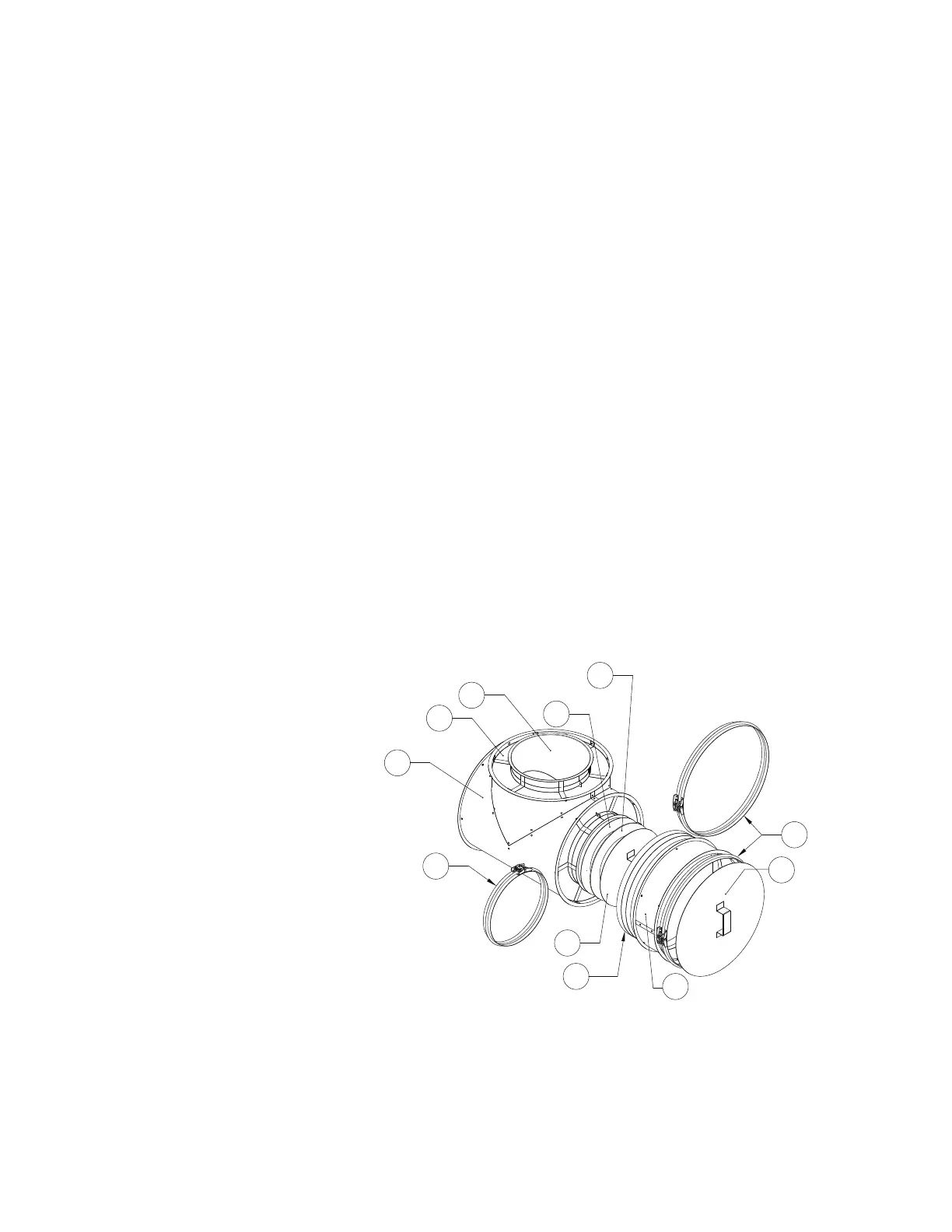
Figure 12 - Access Door Assembly
1. Inner Duct Tee
2. Grease Dam (Inside Blank)
3. Gasket
4. Outer V-band
5. Outer Access Door
6. Outer Shell
7. 3-Layer Access Door Insulation
8. Inner Access Door
9. Inner V-band
10. Outer Duct Shell
11. Insulation