39
Annular Distance – Fire Stop
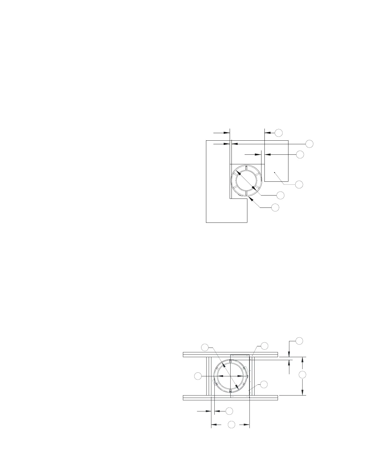
Grease ducts are to be installed eccentrically or concentrically within the fire stop system. The annular
space between the grease duct and the periphery of the opening shall be a minimum of 1” to a maximum
of 2” for 1 and 2 hour fire rated floor and wall assemblies. Grease duct will be rigidly supported on both
sides of the floor and or wall assembly. The F and T rating for the fire stop systems shown below are rated
for 2 hours. The fire stop ratings are applicable only when Specified Technologies Series SSS Latex
Intumescent (STI Triple S) Sealant is used. Annular distance is measured perpendicular from the outside
of the grease duct to the periphery of the opening.
Figure 26 - Annular Distance
Annular Distance – 2R Type HT Clearance
Chimney clearance plates are used to maintain clearance to combustibles for 2R Type HT listed chimneys.
These clearance plates are not a substitute for through penetration and fire stop plates. Chimney
clearance plates are designed to center the chimney in the recommend opening and maintain 2” clearance
to combustibles, refer to Figure 27. Chimney clearance plates consist of two half plates; the plates are
designed so they are inserted into the opening. They are installed on the bottom side of the floor. Frame or
cut the opening in the floor, refer to Table 9. Insert the chimney into the opening, and then insert one half
of the clearance plate. Secure the half plate using appropriate hardware for construction per Figure 28.
Insert the second half plate and secure. Once both plates are secure, the chimney will be centered in the
opening with a 2” clearance to combustibles. 2R Type HT chimney requires 2” minimum annular distances
in an unenclosed installation.
WARNING: Clearance (air space) to combustibles must be free from any type of insulation.
Figure 27 - Clearance Plates
1. Floor/Ceiling
2. Duct
A. Outer Diameter Opening Plus 3” Maximum
B. 1” Minimum Distance
C. 2” Maximum Distance
D. Duct Outer Diameter
1. Hardware
2. Combustible Surface
3. Clearance Plates
A. 2” Reduced Clearance
B. 2R Shell plus 4-1/2”
C. 2R Shell Outer Diameter